Lift cylinders for agricultural machinery

A technology for agricultural machinery and oil cylinders, applied in the direction of fluid pressure actuating devices, etc., can solve the problems of shortening the life of the oil cylinder, leakage of the piston gap, and oil cylinder failure, etc., so as to reduce the failure rate of the oil cylinder, avoid early damage, and improve the life of the oil cylinder. Effect

Active Publication Date: 2019-03-08
LOVOL HEAVY IND CO LTD
View PDF6 Cites 0 Cited by
  • Summary
  • Abstract
  • Description
  • Claims
  • Application Information

AI Technical Summary

Problems solved by technology

[0004] But, there is following problem in the lifting oil cylinder of above-mentioned structure: as Figure 1d As shown, when the tractor and other agricultural machinery hosts are stored or transported for a long time, due to the internal leakage of the gap at the piston 3, under the action of gravity, the limit stopper 7 will come into contact with the stem of the shut-off valve 6 as the piston rod 4 descends.
When the lifting operation is started again, the pressure oil at the oil port a of the rodless cavity cannot open the stop valve 6, and the valve stem will easily push the limit stopper 7 to damage or damage the seal, or the limit stopper 7 will push the valve stem to damage. The early damage to the stop valve will cause the failure of the oil cylinder and reduce the life of the oil cylinder

Method used


Image

  • Lift cylinders for agricultural machinery
  • Lift cylinders for agricultural machinery
  • Lift cylinders for agricultural machinery

Examples


Embodiment Construction

[0020] The present invention will be further illustrated in a non-limiting manner below in conjunction with the accompanying drawings and examples.

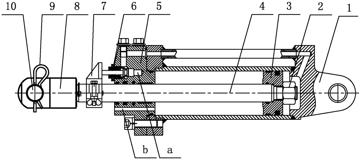
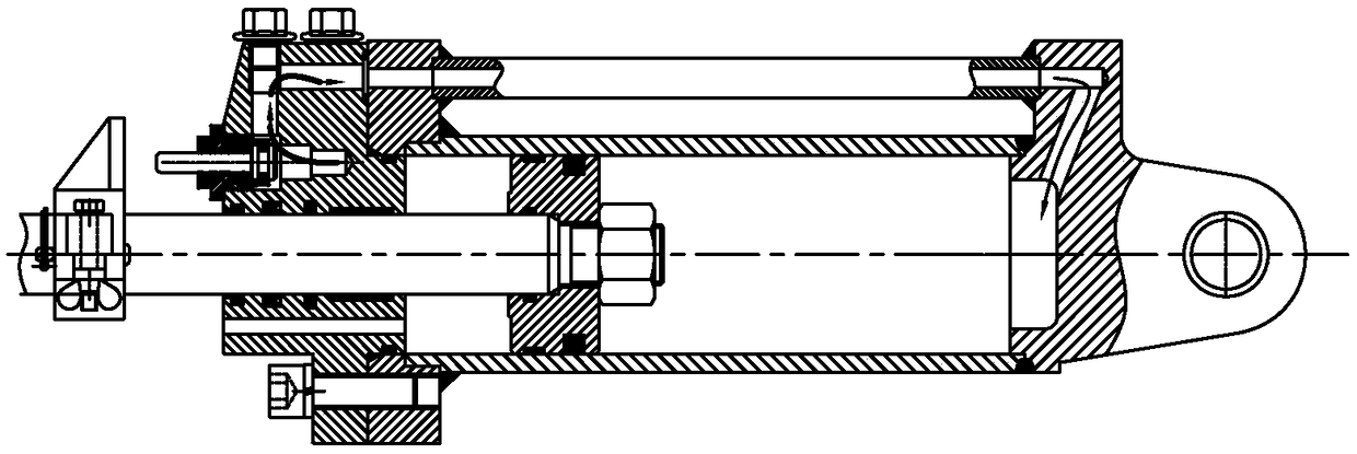
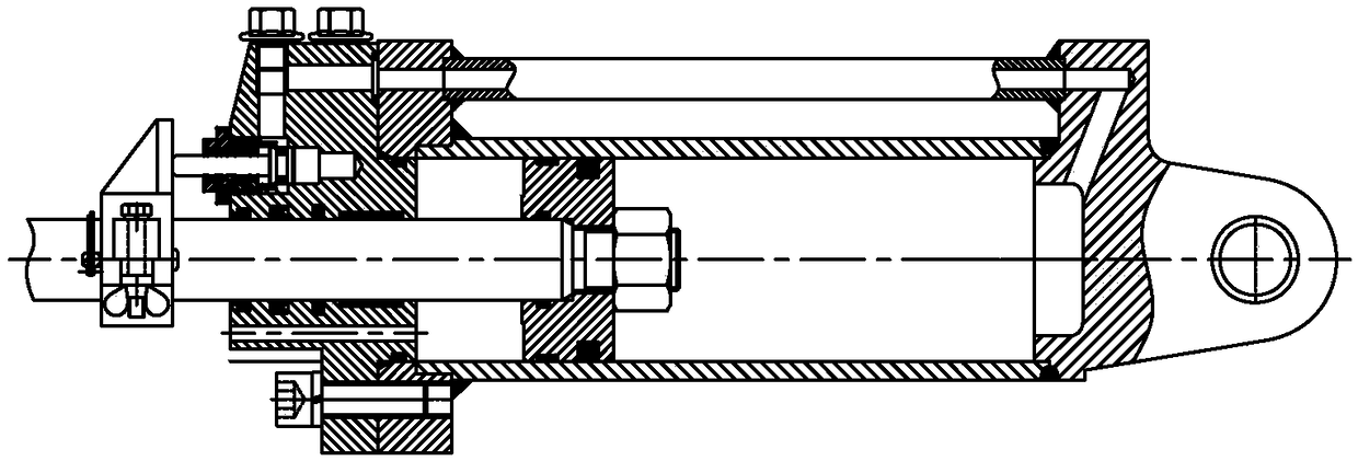
[0021] Such as figure 2 As shown, the lift cylinder for agricultural machinery of the present invention comprises: cylinder barrel 1, cylinder head 5, piston 3, piston rod 4, and piston 3 is positioned at the oil cylinder inner cavity that cylinder head 5 and cylinder barrel 1 surround, and piston 3 will oil cylinder The inner cavity is divided into a rod cavity and a rodless cavity. The piston rod 4 passes through the cylinder head 5 and is connected to the piston 3, and is locked by the lock nut 2. A limit stopper 7 is provided on the outer rod section of the piston rod 4, and the cylinder The cover 5 is provided with a rod chamber oil port b and a rodless chamber oil port a, the rod chamber oil port b communicates with the rod chamber, and the rodless chamber oil port a communicates with the rodless chamber through the rodles...


PUM


Abstract

The invention discloses a lifting oil cylinder for agricultural machinery. The lifting oil cylinder for the agricultural machinery comprises a cylinder barrel, a cylinder cover, a piston and a piston rod; the external rod section of the piston rod is provided with a limiting stop clamp; a rod cavity oil port and a rodless cavity oil port are formed in the cylinder cover; the rodless cavity oil port communicates with a rodless cavity through a rodless cavity oil channel; a stop valve is arranged at the rodless cavity oil port; a connecting channel communicating with the rodless cavity oil port and the rodless cavity oil channel is further formed in the cylinder cover; and a check valve is arranged in the connecting channel. According to the lifting oil cylinder for the agricultural machinery, after a main engine of the lifting oil cylinder for the agricultural machinery is adopted for storing or transporting for a long time, when the lifting operation is started again, oil liquid of the rodless cavity oil port bypasses the stop valve, firstly the check valve is opened so that the oil liquid can enter the rodless cavity, when the oil liquid in the rodless cavity pushes the piston rod to be lifted to a certain position, the stop valve can be normally opened, the piston rod is continuously lifted, and therefore the phenomena that a valve rod abuts against and damages the limiting stop clamp or damages a sealing part, and the limiting stop clamp abuts against and damages the stop valve can be avoided, the failure rate of the oil cylinder can be reduced, and the service life of the oil cylinder can be prolonged.

Description

technical field [0001] The invention relates to the technical field of agricultural machinery, in particular to a lifting cylinder for agricultural machinery. Background technique [0002] Tractor is an indispensable mechanical equipment in agricultural production. It can be used for arable land, sowing, fertilization, transportation, etc. It is mainly composed of driving system, steering system, power shifting system, and lifting system. The tractor lifting hydraulic system consists of hydraulic pumps, lifting cylinders and control valves. The lifting cylinder is an important executive component, such as figure 1 As shown, the existing lifting cylinder is mainly composed of a cylinder barrel 1, a lock nut 2, a piston 3, a piston rod 4, a cylinder head 5, a stop valve 6, a limit stopper 7, a connecting fork 8, a beta stop ring 9, a pin Shaft 10 and other components are composed, and its working principle is as follows: [0003] Such as Figure 1a As shown, under the lifti...

Claims


Application Information

Patent Timeline
Patent Type & Authority Patents(China)
IPC IPC(8): F15B15/14
CPCF15B15/1433F15B15/1438F15B15/1447
Inventor 庞清荣李天富张健付文静
Owner LOVOL HEAVY IND CO LTD
Why Eureka
Try Eureka