
Cover parts for internal combustion engines

A technology for cover parts and internal combustion engines, which is applied in the direction of engine components, lubricating parts, engine lubrication, etc., can solve the problems of increased weight of the chain cover, and achieve the effects of weight reduction, vibration suppression, and efficient lubrication

Active Publication Date: 2019-05-28
HONDA MOTOR CO LTD
View PDF4 Cites 0 Cited by
  • Summary
  • Abstract
  • Description
  • Claims
  • Application Information

AI Technical Summary

Problems solved by technology

[0005] However, in the invention described in the above-mentioned Patent Document 1, the weight of the chain cover increases in accordance with the provision of the first rib and the second rib, and not only that, oil that flows down due to gravity may accumulate in the first rib and the second rib. The intersection of the second rib does not flow down smoothly

Method used


Image

  • Cover parts for internal combustion engines
  • Cover parts for internal combustion engines
  • Cover parts for internal combustion engines

Examples


Embodiment Construction

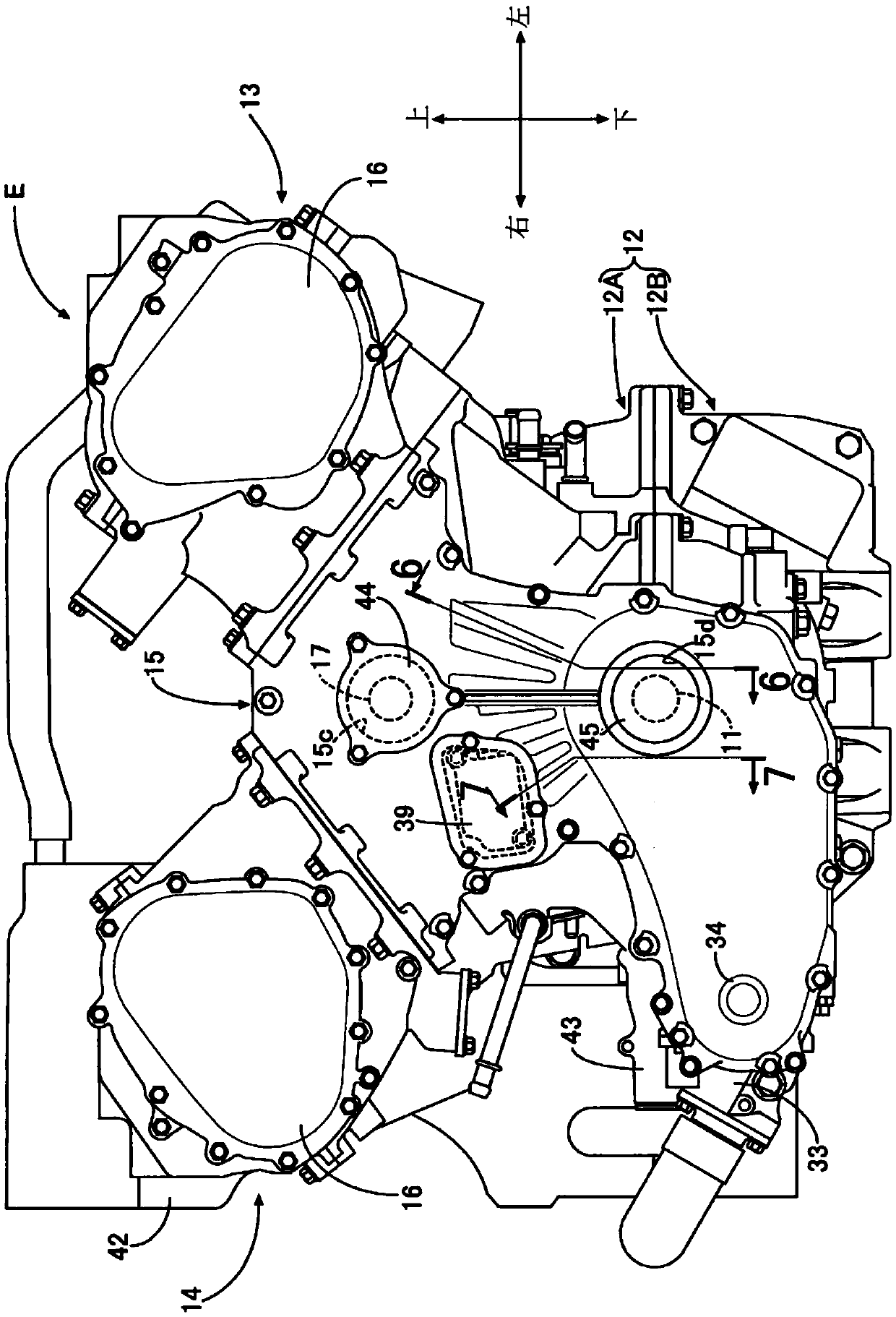
[0025] Below, according to Figure 1 to Figure 7 Embodiments of the present invention will be described. The front-back direction, left-right direction, and up-down direction in this manual are defined based on the driver sitting in the driver's seat.

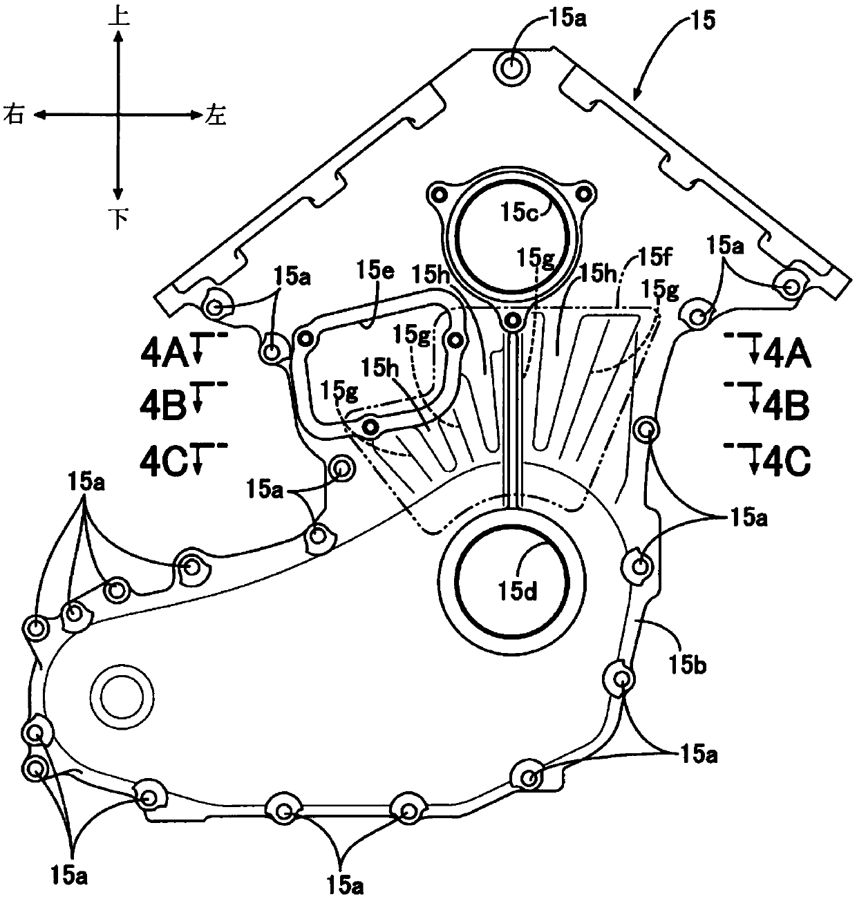
[0026] Such as figure 1 as well as figure 2 As shown, the V-type multi-cylinder internal combustion engine E is mounted on the vehicle body so that the axis of the crankshaft 11 is along the front-rear direction, and the crankcase 12 is formed by integrating the crankcase upper half 12A and the crankcase lower half 12B In this configuration, the left cylinder 13 and the right cylinder 14 protrude obliquely upward in a V shape from the upper portion of the crankcase upper half 12A. The front surface of the crankcase 12 is covered with a detachable main chain cover 15 , and the front openings of the left and right cylinders 13 , 14 are covered with detachable sub chain covers 16 , 16 , respectively.

[0027] The crankshaft 1...


PUM


Abstract

The present invention provides a cover member of an internal combustion engine capable of increasing the rigidity of the cover member of an internal combustion engine to suppress vibration and smoothly guiding oil flowing down the cover member to a through hole supporting a shaft. The cover member (15) installed on the crankcase (12) of the internal combustion engine (E) has: a through hole (15d), which supports the shaft (11) to rotate freely; Above, it bulges toward the inside of the cover member; and a plurality of groove portions (15g), which extend radially from the through hole in a manner connecting the upper and lower portions of the inner surface side of the bulged portion, therefore, not only does not need to set an increased weight The ribs of the bulge (15f) can increase the rigidity of the cover member to suppress vibration through the groove portion (15g) of the bulge (15f), and the oil inside the crankcase (12) can be driven along the bulge (15f) by gravity. The grooves (15g) are gathered around the through hole (15d), so that the rotating shaft (11) can be efficiently lubricated.

Description

technical field [0001] The invention relates to a cover part to be mounted on the casing of an internal combustion engine. Background technique [0002] According to the following patent document 1, it is known that a first rib and a second rib protrude from the inner surface of the chain cover of the internal combustion engine, the first rib extends in the direction of the cylinder axis, and the second rib connects the The side edge of the chain cover and the first rib are inclined downward in the direction of the cylinder axis toward the first rib. The rigidity of the chain cover is increased by the first rib and the second rib to suppress vibration, and it will be moved along by gravity. The oil flowing down from the first rib and the second rib is guided to the sprocket provided on the crankshaft to improve the lubricating performance. [0003] prior art literature [0004] Patent Document 1: Japanese Patent Laid-Open No. 2013-113166 [0005] However, in the invention...

Claims


Application Information

Patent Timeline
Patent Type & Authority Patents(China)
IPC IPC(8): F02F7/00
CPCF02F7/0073F01M9/08F16H57/05F02F2007/0075F02F2007/0078F16N2210/33F01M11/0004F01M2011/0083F02F7/0039
Inventor 小岩洋二郎
Owner HONDA MOTOR CO LTD
Learn More