
Pixel compensation circuit for drive display of single-crystal silicon transistor CMOS and display device

A compensation circuit and transistor technology, applied in the field of pixel compensation, can solve the problems of uneven mobility, current inconsistency, current mismatch, etc., and achieve the effect of good display effect, uniform display and uniform brightness

Pending Publication Date: 2017-06-27
CHENGDU JINGSHA TECH
View PDF3 Cites 0 Cited by
  • Summary
  • Abstract
  • Description
  • Claims
  • Application Information

AI Technical Summary

Problems solved by technology

[0002] The ability of OLED to emit light is driven by the current generated by the drive transistor DM, because when the same gray scale voltage is input, different threshold voltages Vth will generate different drive currents, resulting in inconsistency of the drive current, and at the same time, the mobility u will also be uneven , causing current inconsistencies
[0003] When the glass panel TFT drives the display, the uniformity of the threshold voltage Vth on the TFT process is very poor. At the same time, the threshold voltage Vth also drifts, the mobility u is uneven, and the IR-drop of the operating voltage Vdd (voltage drop caused by multiplying the current by the resistance) It has always existed, so the brightness uniformity of the traditional 2T1C circuit has always been poor
[0004] When the display is driven by single-crystal silicon wafer mos, there will also be some slight threshold voltage Vth, uneven mobility u, and current mismatch problems, and the IR-drop of Vdd will always exist
In this way, the uniformity of the traditional 2T1C circuit is not good, and the PPI is always low

Method used


Image

  • Pixel compensation circuit for drive display of single-crystal silicon transistor CMOS and display device
  • Pixel compensation circuit for drive display of single-crystal silicon transistor CMOS and display device
  • Pixel compensation circuit for drive display of single-crystal silicon transistor CMOS and display device

Examples


Embodiment Construction

[0044] In order to describe the technical features and functions of the present invention in detail, and to implement them according to the content of this specification, the following further describes the implementation modes of the present invention.

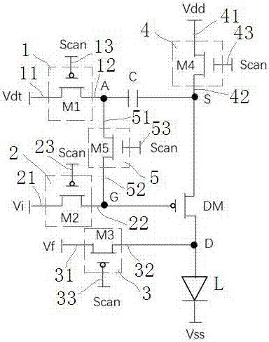
[0045] figure 1 An embodiment of a single crystal silicon transistor CMOS drive display pixel compensation circuit among the numerous embodiments of the present invention is exemplarily shown. The pixel compensation circuit driven by the single crystal silicon transistor CMOS includes a drive transistor DM, a capacitor C, a first switch unit 1 , a second switch unit 2 , a third switch unit 3 , a fourth switch unit 4 and a fifth switch unit 5 .

[0046] The drain of the driving transistor DM is electrically connected to the anode of the light emitting device L.

[0047] One end of the capacitor C is electrically connected to the source of the driving transistor DM.

[0048] The first switch unit 1 includes first, second and ...


PUM


Abstract

The invention provides a pixel compensation circuit for the drive display of a single-crystal silicon transistor CMOS and a display device, which comprises a driving transistor, a capacitor, a first switching unit, a second switching unit, a third switching unit, a fourth switching unit and a fifth switching unit. The first end of the first switching unit is used for inputting a data signal. The first end of the second switching unit is used for inputting a first reference voltage. The first end of the third switching unit is used for inputting a second reference voltage. The first end of the fourth switching unit is electrically connected with a working voltage end. The second end of the fourth switching unit is electrically connected with the source electrode of the driving transistor. The first end of the fifth switching unit is electrically connected with the second end of the first switching unit. The second end of the fifth switching unit is electrically connected with the second end of the second switching unit. A first control signal is input through the third ends of the first, second and third switching units. The first control signal is input through the third ends of the fourth and fifth switching units or a second control signal is input through the third ends of the fourth and fifth switching units. According to the technical scheme of the invention, the influence of the drifting phenomenon of a threshold voltage on light-emitting devices during the light-emitting process is avoided. As a result, the purposes of display uniformity, consistent brightness and the like can be achieved.

Description

technical field [0001] The invention relates to a pixel compensation technology, in particular to a pixel compensation circuit and a display device for display driven by a single crystal silicon transistor CMOS. Background technique [0002] The ability of OLED to emit light is driven by the current generated by the drive transistor DM, because when the same gray scale voltage is input, different threshold voltages Vth will generate different drive currents, resulting in inconsistency of the drive current, and at the same time, the mobility u will also be uneven , causing current inconsistencies. [0003] When the glass panel TFT drives the display, the uniformity of the threshold voltage Vth on the TFT process is very poor. At the same time, the threshold voltage Vth also drifts, the mobility u is uneven, and the IR-drop of the operating voltage Vdd (voltage drop caused by multiplying the current by the resistance) It has always existed, so the brightness uniformity of the...

Claims


Application Information

Patent Timeline
IPC IPC(8): G09G3/3233G09G3/3266
CPCG09G3/3233G09G3/3266
Inventor 吴素华黎守新
Owner CHENGDU JINGSHA TECH
Learn More