
ADRC (Active disturbance rejection controller)-PD compensation control system and method for time delay process

A technology of ADRC-PD and compensation control, which is applied in general control system, control/regulation system, program control, etc., can solve the problems of lagging system control difficulty, advanced controller structure complexity, etc., to improve tracking control performance and Effect

Active Publication Date: 2017-06-27
北京赛普泰克技术有限公司
View PDF13 Cites 8 Cited by
  • Summary
  • Abstract
  • Description
  • Claims
  • Application Information

AI Technical Summary

Problems solved by technology

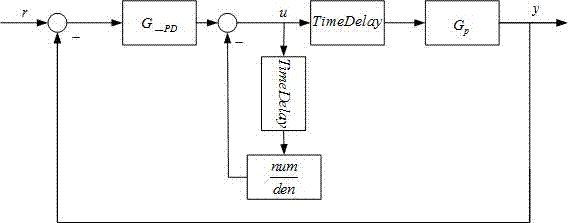
[0003] Aiming at the problems that the control of the lagging system is difficult and the structure of the advanced controller is complex, the present invention provides an ADRC-PD compensation control system and method for the lagging process. The state observer designs the ADRC compensation control module and the PD control module for the disturbance and nonlinear part (including the time-delay part) in the time-delay system, and according to the closed-loop hybrid sensitivity H ∞ The minimum norm is the index, and the parameters of ADRC compensation control module and PD control module are optimized and designed

Method used


Image

  • ADRC (Active disturbance rejection controller)-PD compensation control system and method for time delay process
  • ADRC (Active disturbance rejection controller)-PD compensation control system and method for time delay process
  • ADRC (Active disturbance rejection controller)-PD compensation control system and method for time delay process

Examples


Embodiment 1

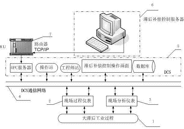
[0045] Apply the present invention to a factory to absorb and stabilize industrial production equipment, and refer to the hardware structure diagram of the equipment figure 1 , refer to the process flow of the device Figure 5 . The device mainly controls the temperature of the rectification tower bottom by adjusting the steam flow rate. Due to the hysteresis of the temperature detection, the difficulty of control is increased.

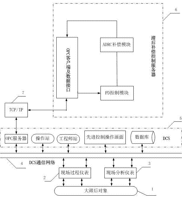
[0046] refer to figure 2 , an ADRC-PD compensation control system and method for a time lag process, including a field instrument connected to the device, a Yokogawa CS3000DCS system, and a DELL 1900 server as a lag compensation server. The lag compensation server includes: an OPC client data communication module and a database interface module. Use the OPC client data acquisition module to collect tower kettle temperature, steam flow and valve opening.

[0047] Through open-loop identification, the open-loop transfer function of the identified o...

Embodiment 2

[0053] Apply the present invention to an industrial methane production device in a factory, and refer to the hardware structure diagram of the device figure 1 , refer to the process flow of the device Figure 7 . The device controls the liquid level of a liquid storage tank. Due to the needs of production, there is a buffer tank in the previous stage of the liquid storage tank. The liquid level of the liquid storage tank is controlled through the feed valve of the buffer tank. There is a large hysteresis in the liquid level control of a multi-capacity device like this.

[0054] Through open-loop identification, the open-loop transfer function of the identified object is:

[0055]

[0056] ADRC-PD compensation control module. It is used for the compensation control of the lagging object, optimizes and calculates the appropriate output value for the feed valve, so that the opening of the valve meets the control requirements of the liquid level.

[0057] After using the pr...


PUM


Abstract

The invention discloses an ADRC (Active disturbance rejection controller)-PD compensation control system for a time delay process, which comprises a field process instrument connected with the time delay process, a field analysis instrument, a distributed control system (DCS) and a time delay compensation control server, wherein the time delay compensation control server comprises an OPC client, a data interface module, an ADRC time delay compensation module, a PD (Proportional-Derivative) control module, and an ADRC time delay compensation module and PD control module parameter optimization design method. The invention provides the ADRC-PD compensation control system and the method for the time delay industrial process.

Description

technical field [0001] The invention relates to the field of industrial process control, and is a real-time control system aiming at lagging output of a controller, and the controller adopts an ADRC-PD compensation control method. Background technique [0002] In industrial process control, due to the delay in the transmission of materials or energy or the lag in the output of the controller, the controlled object has the nature of pure hysteresis. When controlling the ratio of the pure lag time τ to the time constant T When using a conventional PID controller, the control process will be seriously overshooted and the stability will be deteriorated. For objects with a large lag, in order to overcome the lag, a stronger differential action is usually added to the PID controller, but the differential will amplify the disturbance and easily lead to system instability. For the control of delay systems, the SMITH predictor is one of the classic solutions (Lee T H, Wang Q G, Ta...

Claims


Application Information

Patent Timeline
Patent Type & Authority Applications(China)
IPC IPC(8): G05B19/418
CPCG05B19/4184Y02P90/02
Inventor 赵众李普贤
Owner 北京赛普泰克技术有限公司
Learn More