
A stick-slip test device

A technology of motion test and rotating device, which is applied in the field of tribology, can solve the problems of lack of test verification, achieve high measurement accuracy, improve system stability and processing accuracy, and reduce vibration

Active Publication Date: 2019-01-29
SOUTHWEST JIAOTONG UNIV
View PDF8 Cites 0 Cited by
  • Summary
  • Abstract
  • Description
  • Claims
  • Application Information

AI Technical Summary

Problems solved by technology

[0003] At present, the research on stick-slip motion at home and abroad mostly focuses on numerical research, lacking experimental verification

Method used


Image

  • A stick-slip test device

Examples


Embodiment Construction

[0039] The present invention will be further described below in conjunction with the accompanying drawings and specific embodiments.

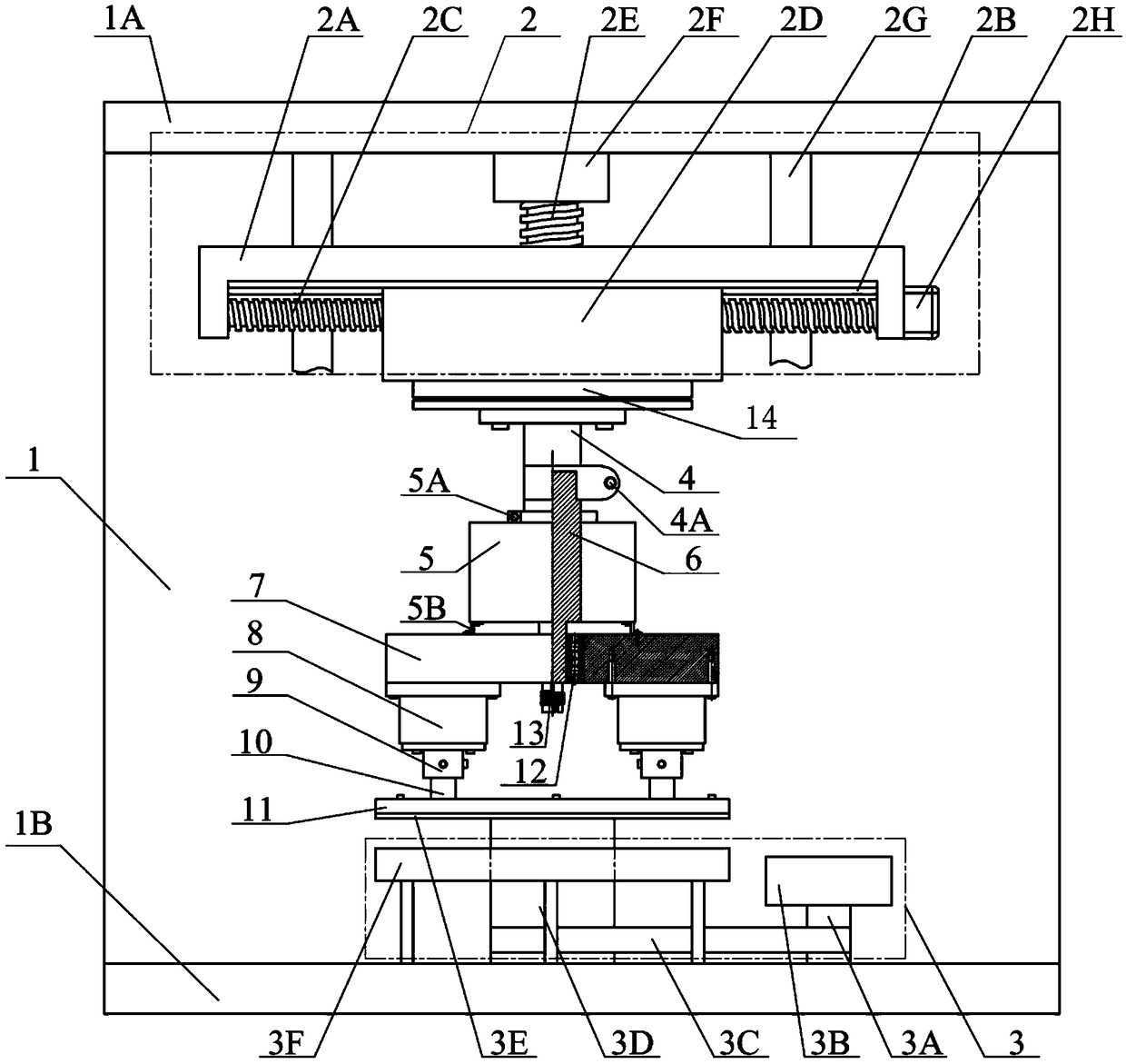
[0040] The schematic diagram of the device structure in the embodiment of the present invention is as follows figure 1As shown, a two-dimensional mobile platform 2 is installed on the bottom of the top plate 1A of the machine base 1, a rotating device 3 is installed on the bottom plate 1B of the machine base 1, the lower friction member 11 is installed on the rotating device 3, and the strain gauge force sensor 14 is fixed on the two-dimensional mobile At the bottom of the platform 2, the flange 4 is in contact with the bottom surface of the strain gauge force sensor 14 and fixed to the bottom of the strain gauge force sensor 14 by screws, the fixed shaft 6 passes through the central hole of the encoder 5 and is fixed thereto, and one end is fixed on the flange The other end of the inner hole of the disk 4 is fixed in the central inner hole of ...


PUM


Abstract

A stick-slip motion test device belongs to the technical field of tribology. The device provided by the present invention controls the movement of the two-dimensional mobile platform 2 in the horizontal direction and the vertical direction through the control system, so that the strain gauge force sensor 14 presses the fixed shaft 6 and then the clamp 9 so that the upper friction member 10 and the lower friction member 11 maintains the set normal load after contact, and the control system controls the rotating device 3 to rotate at the set speed and direction, so that relative friction occurs between the upper friction piece 10 and the lower friction piece 11 . The present invention adopts two upper friction parts 10, which can effectively avoid the phenomenon of uneven contact between the upper friction part and the lower friction part, thereby avoiding uneven stress distribution on the contact surface; this device can study friction parts of different materials and different normal forces , different speeds and other related parameters, the friction force, displacement, normal force, speed change law, so as to study the mechanism and influencing factors of stick-slip motion.

Description

technical field [0001] The invention belongs to the technical field of tribology, and in particular relates to a stick-slip motion test device. Background technique [0002] Stick-slip motion is a kind of friction phenomenon of "movement-rest-re-movement-re-rest" caused by different values ​​of dynamic and static friction coefficients under certain conditions. It is a self-excited friction between two sliding objects. jumping motion. As a typical friction phenomenon, stick-slip motion widely exists in mechanical systems. It is one of the main causes of system vibration, which will bring mechanical system chatter, limit cycle oscillation, and sharp noise in the braking system during braking. , Numerous negative problems such as poor machining accuracy at low speed of CNC machine tools. Therefore, in order to improve the stability of the mechanical system and reduce vibration, improve the machining accuracy of machine tools, reduce frictional vibration noise and develop an e...

Claims


Application Information

Patent Timeline
Patent Type & Authority Patents(China)
IPC IPC(8): G01M13/00
CPCG01M13/00
Inventor 莫继良王晓翠张琦唐斌朱旻昊周仲荣
Owner SOUTHWEST JIAOTONG UNIV
Learn More