
A crankshaft transfer frame box

A frame box and crankshaft technology, which is applied in the direction of containers, packaging items, special packaging items, etc., can solve the problem of no crankshaft turnover frame box, etc., and achieve the effect of reasonable structure, neat arrangement and easy operation.

Inactive Publication Date: 2017-06-27
TIANRUN IND TECH CO LTD
View PDF0 Cites 0 Cited by
  • Summary
  • Abstract
  • Description
  • Claims
  • Application Information

AI Technical Summary

Problems solved by technology

So far, there is no literature report on a dedicated crankshaft turnover frame box

Method used


Image

  • A crankshaft transfer frame box
  • A crankshaft transfer frame box

Examples


Embodiment Construction

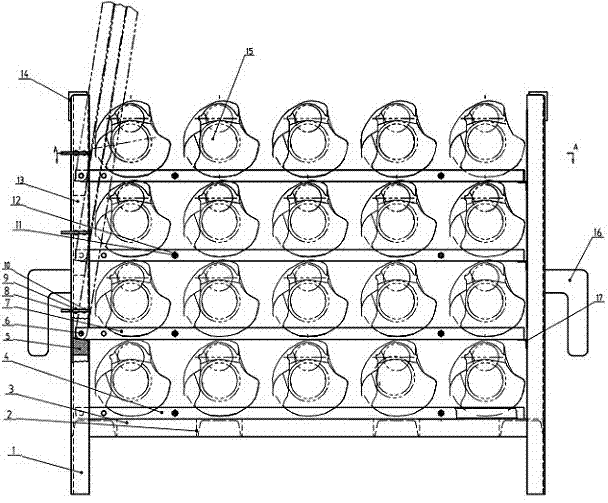
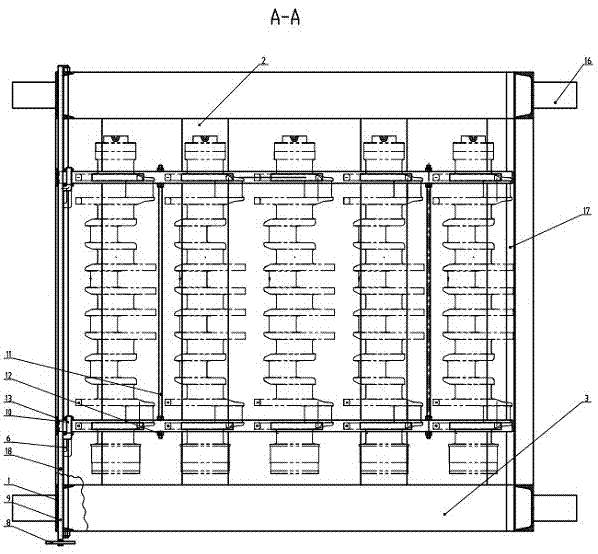
[0016] from figure 1 , figure 2 It can be seen from the figure that a crankshaft turnover frame box includes a base, a pillar 1, a reinforced top plate 14, a trough vertical plate 13, a fixed partition 4, a movable partition 7, a support plate 17, and the like. The base is welded by four horizontal connecting plates 2 and two longitudinal connecting plates 3 . Four columns 1 are vertically welded on the four corners of the base, and two reinforced top plates 14 are arranged on the left and right sides respectively, and the tops of the left and right columns are welded and fixed horizontally. The base, the four pillars and the reinforced top plate form a frame like this. The fixed partition 4 is placed on the transverse connecting plate 2 to form the crankshaft spacer on the first floor at the bottom.

[0017] The present invention is characterized in that: the two trough-type vertical plates 13 are vertically fixed between the left side transverse connecting plate 2 and th...


PUM


Abstract

The invention provides a crankshaft transfer frame box comprising a pedestal, stand pillars, a reinforced top plate, grooved stand plates, fixed separating plates, movable separating plates and supporting plates. The pedestal is formed by welding cross connecting plates and longitudinal connecting plates. The two grooved stand plates are vertically fixed between the cross connecting plate on the left side and the reinforced top plate; the movable separating plates are installed in layers; two movable separating plates in each layer are movably connected with the grooved stand plates via hinge shafts and are supported on the grooved stand plates, with the right ends being supported by the supporting plates; the supporting plates are arranged between the two stand pillars on the right side in layers; push-pull rods penetrating the grooved stand plates transversely are arranged between the stand pillars on the left side in layers; the push-pull rods are provided with insertion pins which are located above the hinge shafts on the grooved stand plates and are corresponding to insertion pin holes in the grooved stand plates and the movable separating plates so as to locate the movable separating plates which are turned to stand in an inclined manner. The crankshaft transfer frame box is reasonable in structure, facilitates crankshaft loading and unloading operations, is high in carrying efficiency and is suitable for carrying of various kinds of crankshafts.

Description

technical field [0001] The invention relates to a transport turnover tool between crankshaft processing and heat treatment, in particular to a crankshaft turnover frame box. Background technique [0002] We know that in the process of engine crankshaft processing, due to the large variety, centralized heat treatment is often required, so it must be transported to heat treatment equipment for centralized treatment. Since the temperature of the residual heat after heat treatment of the crankshaft is high, it is required to be transported by a forklift, and the transport tools are resistant to high temperatures. . It is also required that some processed surfaces should not be damaged during turnover, and the number of placements can be seen at a glance, with high efficiency and neat appearance. So far, there is no literature report on a dedicated crankshaft turnover frame box. Contents of the invention [0003] The technical problem to be solved by the present invention is ...

Claims


Application Information

Patent Timeline
Patent Type & Authority Applications(China)
IPC IPC(8): B65D25/06B65D85/68
CPCB65D25/06B65D85/68B65D2585/6877
Inventor 周扬帆李庆让谭富明马明亮宋文友
Owner TIANRUN IND TECH CO LTD
Learn More