Calibration plate used for binocular camera calibration, calibration method and calibration system thereof
A technology of a binocular camera and a calibration method, which is applied in the field of camera calibration, can solve the problems of complicated operation, high cost and insufficient calibration accuracy, and achieves the effect of improving the calibration accuracy.
- Summary
- Abstract
- Description
- Claims
- Application Information
AI Technical Summary
Problems solved by technology
Method used
Image
Examples
Embodiment 1
[0092] A calibration board for binocular camera calibration, including an electronic device terminal for receiving resolution information and outputting planar checkerboard image drive information according to the resolution, and also includes a terminal for receiving planar checkerboard image drive information and displaying a planar checkerboard grid image display.
[0093] Calibration Target is used in machine vision, image measurement, photogrammetry, 3D reconstruction and other applications to correct lens distortion; determine the conversion relationship between physical size and pixel; and determine the three-dimensional geometric position of a point on the surface of a space object and its position The relationship between corresponding points in the image requires the establishment of a geometric model of camera imaging. The geometric model of the camera can be obtained through the calculation of the camera with a fixed-pitch pattern array plate and the calculation of...
Embodiment 2
[0100] A binocular camera calibration method, comprising the following steps:
[0101] Step 1: Connect the device with the camera to the computer through the USB cable, and wait for the camera to enter the normal working state.
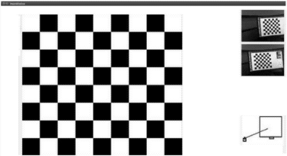
[0102] Step 2: Obtain the resolution of the PC monitor, make a checkerboard image corresponding to the resolution, and display the checkerboard image as a calibration board. Make corresponding checkerboard images according to the monitors with different resolutions, so that the PC can display a clear enough calibration checkerboard and improve the calibration accuracy. Calibrate the checkerboard image as figure 1 shown.
[0103] Step 3: The calibration checkerboard image is preprocessed by the image preprocessing module of the calibration system. Perform preprocessing operations such as denoising and enhancement on the image.
[0104] Step 4: Control to turn on the camera and start shooting checkerboard images for camera calibration.
[0105] Ste...
Embodiment 3
[0168] The calibration system using the above calibration board includes:
[0169] Chessboard image production module: used to obtain the resolution of the display, and make a corresponding plane checkerboard image according to the resolution of the display, and display the checkerboard image as a calibration board in the form of a display;
[0170] Image acquisition module: used to control the camera to shoot and display the display of the plane checkerboard image from multiple perspectives, the picture acquired by the left camera is the left image, and the picture acquired by the right camera is the right image;
[0171] Feature point matching module; used to detect and extract the feature points of the left image and the right image, and then use the sequential matching method to match the feature points of the plane checkerboard image displayed on the display with the left image and the right image to obtain the matched features point;
[0172] Calibration module: used to...
PUM
 Abstract
Description
Claims
Application Information
 - R&D
- Intellectual Property
- Life Sciences
- Materials
- Tech Scout
- Unparalleled Data Quality
- Higher Quality Content
- 60% Fewer Hallucinations
Browse by: Latest US Patents, China's latest patents, Technical Efficacy Thesaurus, Application Domain, Technology Topic, Popular Technical Reports.
© 2025 PatSnap. All rights reserved.Legal|Privacy policy|Modern Slavery Act Transparency Statement|Sitemap|About US| Contact US: help@patsnap.com


