Rankine Cycle System For Vehicle
A cycle system and vehicle technology, applied in the field of Rankine cycle systems for vehicles, can solve problems such as the reduction of heat recovery efficiency, and achieve the effects of suppressing the decline in efficiency, temperature, and heat dissipation.
- Summary
- Abstract
- Description
- Claims
- Application Information
AI Technical Summary
Problems solved by technology
Method used
Image
Examples
Embodiment approach 1
[0076] 1. Structure of the Rankine cycle system
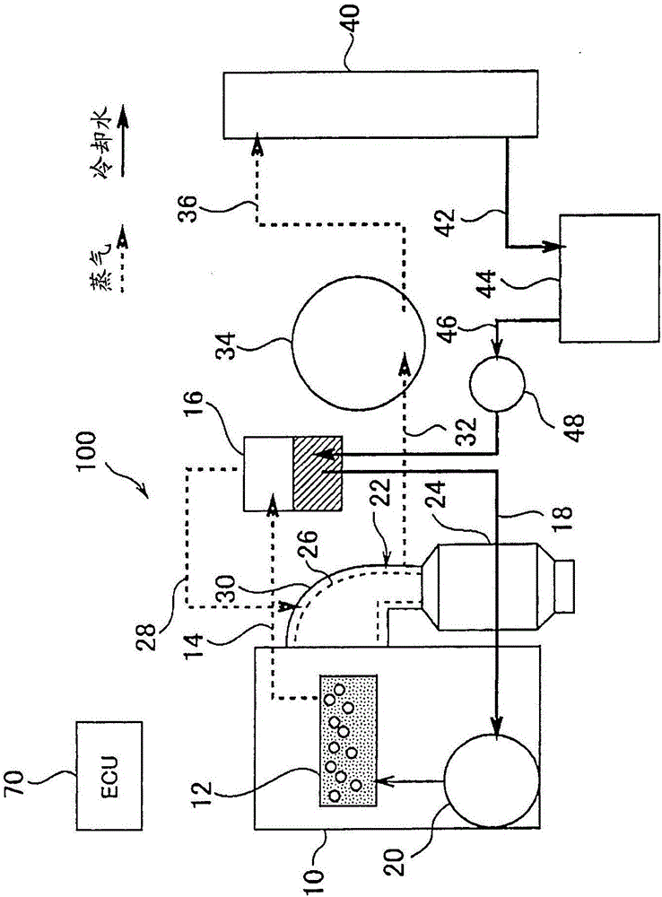
[0077] figure 1 It is a diagram showing the configuration of the Rankine cycle system 100 according to the first embodiment. The Rankine cycle system 100 of Embodiment 1 is configured as a Rankine cycle system for a vehicle that includes an internal combustion engine (engine) 10 and is mounted on a vehicle. The type and structure of the engine 10 are not limited. However, in the cylinder block and the cylinder head of the engine 10, a refrigerant passage 12 through which the refrigerant circulating in the engine 10 flows is formed. The refrigerant flow path 12 includes a water jacket surrounding the cylinder. Engine 10 is cooled by exchanging heat with the refrigerant flowing in refrigerant passage 12 . In this embodiment, water is used as the refrigerant.
[0078] The engine 10 is cooled by using waste heat of the engine 10 to boil the refrigerant flowing through the refrigerant passage 12 to vaporize part of the refriger...
Embodiment approach 2
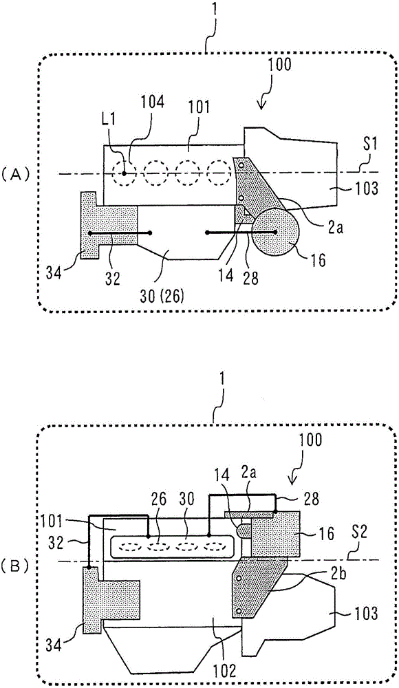
[0106] Next, the Rankine cycle system 110 according to Embodiment 2 will be described. Figure 7 It is a schematic diagram for explaining the fixed structure of the gas-liquid separator 16 in the Rankine cycle system 110 of Embodiment 2. In addition, (A) of the figure shows the top view of the vehicle of this Rankine cycle system, and (B) of the figure shows the front view of the vehicle of the Rankine cycle system mounted on a vehicle. Moreover, in Figure 7 in, for with figure 2 Common components of the Rankine cycle system 100 according to Embodiment 1 shown are denoted by the same reference numerals.
[0107] In the Rankine cycle system 110 according to Embodiment 2, the gas-liquid separator 16 is arranged in a region above the exhaust side of the engine 10 and at a position overlapping the superheater 30 or the exhaust manifold 26 in a plan view of the vehicle. The gas-liquid separator 16 is fixed to the engine 10 via the brackets 4a, 4b. The brackets 4a, 4b are resp...
Embodiment approach 3
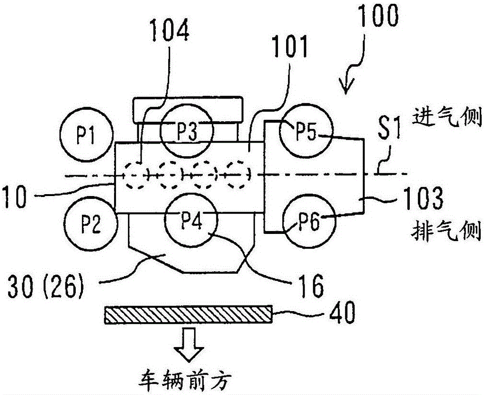
[0111] Next, the Rankine cycle system 120 according to Embodiment 3 will be described. The Rankine cycle system 120 according to the third embodiment is characterized in that the cylinder head 101 and the gas-liquid separator 160 are integrally formed. Figure 8 and Figure 9 It is a schematic diagram for explaining the fixed structure of the gas-liquid separator in the Rankine cycle system 120 of Embodiment 3. It should be noted, Figure 8 A diagram showing a state in which the gas-liquid separator 160 is integrated with the cylinder head 101 viewed from the exhaust side, Figure 9 A diagram showing a disassembled state of the gas-liquid separator 160 and the cylinder head 101 viewed from the intake side.
[0112] As shown in these figures, a refrigerant inlet port 161 is provided in the gas-liquid separator 160 . The inlet port 161 is used to guide the refrigerant led out from the refrigerant passage 12 of the engine 10 to the gas-liquid separator 160 . The inlet port 1...
PUM
 Abstract
Description
Claims
Application Information
 - R&D
- Intellectual Property
- Life Sciences
- Materials
- Tech Scout
- Unparalleled Data Quality
- Higher Quality Content
- 60% Fewer Hallucinations
Browse by: Latest US Patents, China's latest patents, Technical Efficacy Thesaurus, Application Domain, Technology Topic, Popular Technical Reports.
© 2025 PatSnap. All rights reserved.Legal|Privacy policy|Modern Slavery Act Transparency Statement|Sitemap|About US| Contact US: help@patsnap.com


