
Composite metal plate and manufacturing method thereof

A technology of metal composite panels and manufacturing methods, applied in the direction of metal layered products, metal processing equipment, chemical instruments and methods, etc., can solve the problem of damage to the protective coating on the surface of metal panels, shortened service life, difficult coating repair, etc. problems, achieve superior mechanical properties, convenient riveting, and prolong service life

Active Publication Date: 2017-06-23
CENT INT GROUP
View PDF4 Cites 2 Cited by
  • Summary
  • Abstract
  • Description
  • Claims
  • Application Information

AI Technical Summary

Problems solved by technology

During the production of metal composite panels, the three panels are often fixed by welding, and the welding is often done by spot welding, because the welding itself will damage part of the protective coating on the metal panel surface; at the same time, the resulting panel surface Welding deformation will affect the overall appearance quality of the composite panel, and it is time-consuming and labor-intensive to apply a second coating to the surface of the metal panel during use
In the process of using the composite board, due to the difficulty of coating repair at the internal welding position, corrosion will occur at the welding position after long-term use, and the metal composite board will be separated due to corrosion, thereby greatly shortening its service life

Method used


Image

  • Composite metal plate and manufacturing method thereof
  • Composite metal plate and manufacturing method thereof
  • Composite metal plate and manufacturing method thereof

Examples


Embodiment Construction

[0025] The technical solutions of the present invention will be clearly and completely described below in conjunction with the accompanying drawings. Apparently, the described embodiments are some of the embodiments of the present invention, but not all of them. Based on the embodiments of the present invention, all other embodiments obtained by persons of ordinary skill in the art without making creative efforts belong to the protection scope of the present invention.

[0026] In addition, the technical features involved in the different embodiments of the present invention described below may be combined with each other as long as there is no conflict with each other.

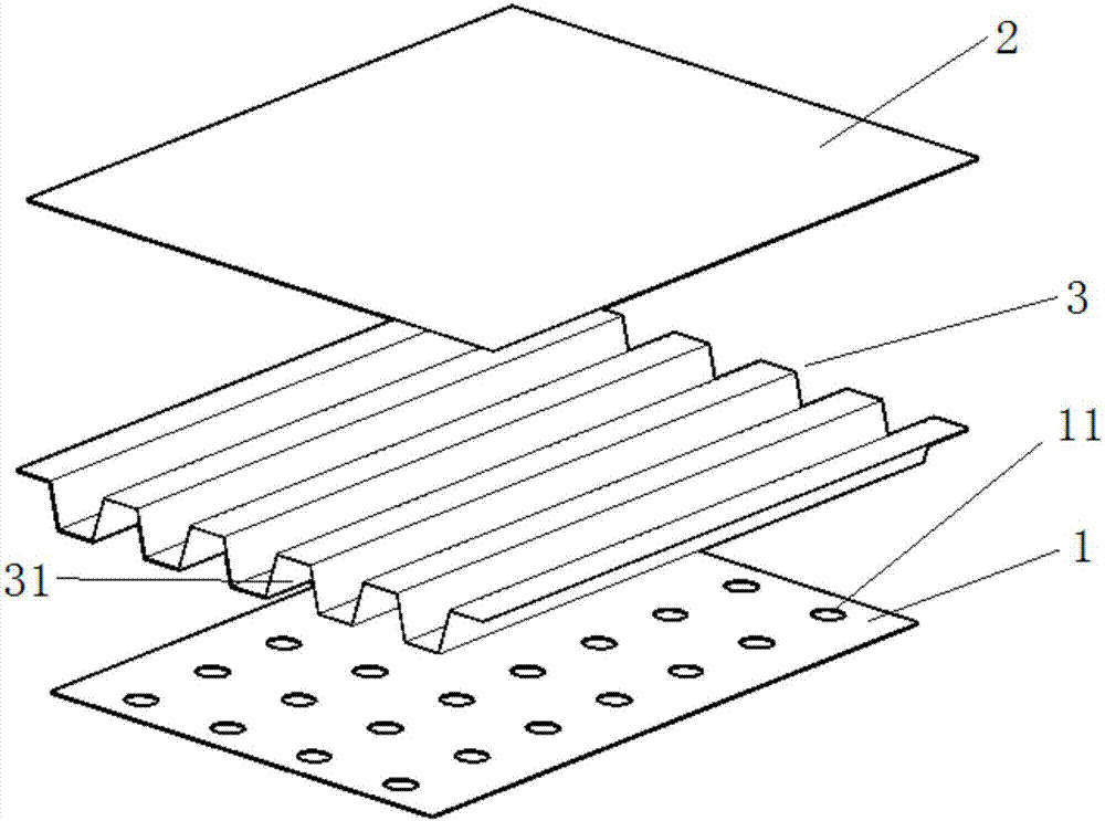
[0027] Such as image 3 As shown, the present invention provides a metal composite panel, comprising a first panel 1, a corrugated panel 3 and a second panel 2, the corrugated panel 3 is arranged between the first panel 1 and the second panel 2, and on the first panel 1 Formed with a plurality of process hol...


PUM

PropertyMeasurementUnit
thicknessaaaaaaaaaa

Abstract

The invention discloses a composite metal plate and a manufacturing method of the composite metal plate. The composite metal plate comprises a first panel, a corrugated panel and a second panel, the corrugated panel is arranged between the first panel and the second panel, a plurality of fabrication holes are formed in the first panel, the first panel is fitted with a lower panel surface of the corrugated panel, the second panel is fitted with an upper panel surface of the corrugated panel, a plurality of stamping riveted structures vertical to the panel surface are formed on the combination surfaces between the first panel and the corrugated panel and between the second panel and the corrugated panel, the riveted structure is a combination part formed in a way that a female mould and a male mould of a riveting tool stamp on the first panel, the second panel and the corrugated panel, and the first panel and the second panel are respectively fixedly connected with the corrugated panel through the riveted structure. Through the plurality of fabrication holes formed in the first panel by the female mould and the male mould of the riveting tool, the first panel and the second panel are respectively rapidly riveted with the corrugated panel, and compared with the existing composite metal plate manufactured through a welding method, the manufactured composite metal plate has better mechanical properties.

Description

technical field [0001] The invention relates to the technical field of metal composite panels, in particular to a metal composite panel and a manufacturing method thereof. Background technique [0002] Existing metal composite panels are composed of an interlayer in the middle and metal plates on both sides of the interlayer. Because of their good mechanical properties, they are often used as roof panels, wall panels and other decorative panels. During the production of metal composite panels, the three panels are often fixed by welding, and the welding is often done by spot welding, because the welding itself will damage part of the protective coating on the metal panel surface; at the same time, the resulting panel surface Welding deformation will affect the overall appearance quality of the composite board, and it will take a lot of time and effort to apply a second coating to the surface of the metal board during use. In the process of using the composite board, due to ...

Claims


Application Information

Patent Timeline
Patent Type & Authority Applications(China)
IPC IPC(8): B32B7/08B32B15/01B32B3/28B32B3/30B32B3/24B21D39/03B21D22/02B21D47/04
CPCB21D22/02B21D39/031B21D47/04B32B3/266B32B3/28B32B3/30B32B7/08B32B15/01B32B2307/714B32B2311/00B32B2419/06B32B2451/00B32B2607/00
Inventor 翟蔗园魏良庆卢兴辉孟文政王吉元
Owner CENT INT GROUP
Learn More