DC motor speed control system and speed detection method thereof

A control system and DC motor technology, applied in the direction of DC motor speed/torque control, control system, excitation or armature current control, etc., can solve the problems of speed detection error, influence on speed measurement accuracy, user burden, etc., and achieve reduction Less complexity, lower production costs, and better accuracy

Inactive Publication Date: 2017-06-20
UNIV OF SHANGHAI FOR SCI & TECH
View PDF3 Cites 7 Cited by
  • Summary
  • Abstract
  • Description
  • Claims
  • Application Information

AI Technical Summary

Problems solved by technology

In the process of speed detection, not only the heavy hammer is easily affected by the bumps of the ground, resulting in a certain error in the detected speed; but also the uneven scale of the indicator dial will also lead to inaccurate display and reading of the speed; the flash speedometer is based on the instrument When the flash frequency is equal to the rotational frequency of the measured object, the flash frequency is the rotational speed of the measured object, but when the light source of the instrument is blocked, it will affect the accuracy of the speed measurement; the photoelectric digital tachometer uses photoelectric sensitive elements to measure and instrument showing speed
However, when the weather is bad, it will affect the working accuracy of the photoelectric sensor, resulting in the error of speed detection
[0004] In addition, most of these detection devices need to be fixed at special positions, which are additional speed detection devices installed on the wheelchair, which not only increases the production cost, but also increases the structural complexity of the wheelchair, which brings inconvenience to the user. burden

Method used


Image

  • DC motor speed control system and speed detection method thereof
  • DC motor speed control system and speed detection method thereof
  • DC motor speed control system and speed detection method thereof

Examples


Embodiment Construction

[0014] In order to make the technical means, creative features, goals and effects of the present invention easy to understand, the following embodiments will specifically illustrate the wheelchair-based DC motor speed control system and its speed detection method of the present invention in conjunction with the accompanying drawings.

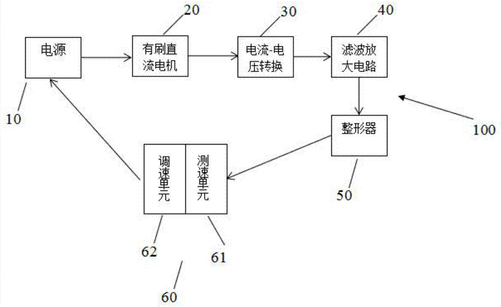
[0015] figure 1 It is a structural schematic diagram of the DC motor speed regulation control system in the embodiment of the present invention.

[0016] Such as figure 1 As shown, the DC motor speed control system 100 includes a power supply 10 , a brushed DC motor 20 , a current-voltage converter 30 , a filter amplifier circuit 40 , a shaper 50 and a microprocessor 60 .

[0017] The power supply 10 is used to supply power to the brushed DC motor 20 .

[0018] The brushed DC motor 20 includes a brush and a commutator. The power supply 10 introduces a DC voltage into the commutator through the brush. The commutator converts the applied DC volt...


PUM


Abstract

The invention provides a DC motor speed control system. The DC motor speed control system comprises a brush DC motor, a power supply, a current-voltage converter, a filter amplification circuit, a shaping device and a microprocessor, wherein the brush DC motor is arranged on a wheelchair, the power supply is used for providing power for the brush DC motor, the current-voltage converter is connected with the brush DC motor and is used for converting a pulse current flowing through the brush DC motor to a pulse voltage, the filter amplification circuit is connected with the current-voltage converter and is used for filtering and amplifying the pulse voltage, the shaping device is connected with the filter amplification circuit and is used for shaping the pulse voltage subjected to filtering and amplification to a square wave, the microprocessor is provided with a speed measurement unit and a speed regulation unit, the speed measurement unit is connected with the shaping device and is used for capturing the square wave to obtain a pulse frequency and calculating a rotational speed of the brush DC motor according to the pulse frequency and a preset rule, and the speed regulation unit is connected with the brush DC motor and is used for adjusting the rotational speed of the brush DC motor so as to further regulate a travelling speed of the wheelchair. The invention also provides a speed detection method for the DC motor speed control system.

Description

technical field [0001] The invention relates to a DC motor speed regulation control system and a speed detection method thereof. Background technique [0002] In the DC motor speed control system, the method of speed closed-loop control is generally used to improve the static performance and dynamic performance of the system. The premise of the speed closed loop is the detection of the speed. At present, the method of detecting the speed is mainly realized by using a centrifugal tachometer, a flash speedometer, and a photoelectric digital tachometer. [0003] The centrifugal tachometer is mainly composed of a centrifuge, a transmission, and an indicating dial, among which most of the centrifuges use a heavy hammer structure. In the process of speed detection, not only the heavy hammer is easily affected by the bumps of the ground, resulting in a certain error in the detected speed; but also the uneven scale of the indicator dial will also lead to inaccurate display and read...

Claims


Application Information

Patent Timeline
Patent Type & Authority Applications(China)
IPC IPC(8): H02P7/29
CPCH02P7/2913
Inventor 李文秀胡杰董祺李新伟喻洪流张林灵
Owner UNIV OF SHANGHAI FOR SCI & TECH
Why Eureka
Try Eureka