
High-voltage DC circuit breaker and test method

A high-voltage direct current and circuit breaker technology, applied in the field of electric power, can solve the problems of lack of direct current circuit breakers, etc., achieve the effect of reducing the rate of rise, reducing the rate of voltage rise, and making it convenient

Inactive Publication Date: 2017-06-20
GUIZHOU POWER GRID CO LTD
View PDF3 Cites 17 Cited by
  • Summary
  • Abstract
  • Description
  • Claims
  • Application Information

AI Technical Summary

Problems solved by technology

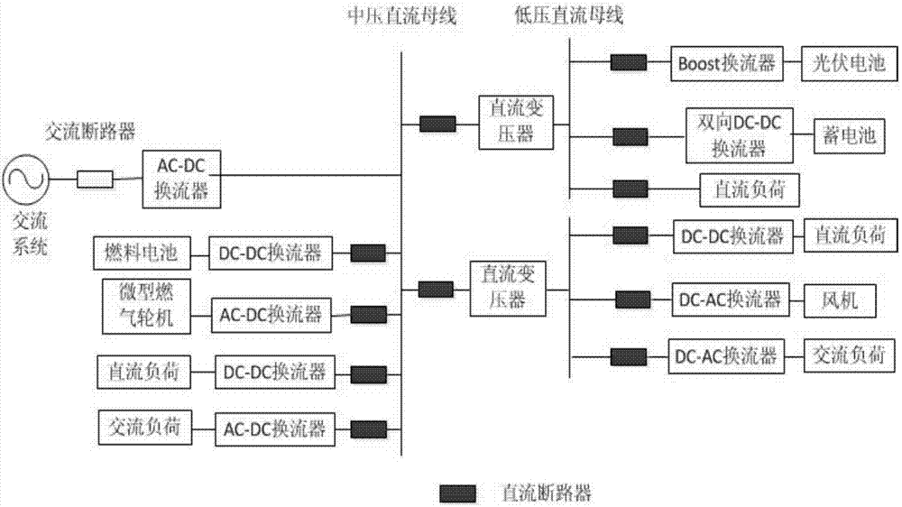
The DC circuit breaker is an important device in the DC micro-grid system, which plays a key role in fault tripping and protection of power equipment in the system. At present, there is a lack of practical DC circuit breakers.

Method used


Image

  • High-voltage DC circuit breaker and test method
  • High-voltage DC circuit breaker and test method

Examples


Embodiment Construction

[0018] The present invention will be further described in detail below in conjunction with the accompanying drawings, but not as any limitation to the present invention.

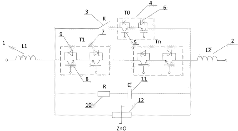
[0019] as attached figure 1 As shown, the embodiment of the present invention: a high-voltage DC circuit breaker consists of a first current-limiting reactor 1, a second current-limiting reactor 2, a fast disconnecting switch 3, an auxiliary switch 4, IGBTs 5, 8, diodes 6, 9. Composed of a solid-state switch 7, a resistor 10, a capacitor 11, and a zinc oxide arrester 12, the first current-limiting reactor (1), the electrical branch and the second current-limiting reactor (2) sequentially form a series circuit.

[0020] The electrical branch includes a first branch, a second branch, a third branch and a fourth branch, and the first branch, the second branch, the third branch and the fourth branch are in parallel.

[0021] The first branch is connected in series with the fast isolating switch 3 and the auxil...


PUM


Abstract

The invention discloses a DC circuit breaker and a test method. The DC circuit breaker is formed by connecting two current limiting reactors in series to the two ends of four parallel branches. Of the four parallel branches, the first branch is a main branch, and is composed of a quick isolation switch K and an auxiliary quick switch T0 connected in series. The second branch is a transfer branch, and is composed of a solid state switch. The solid state switch is composed of a plurality of IGBT modules connected in series. Each IGBT module is composed of two IGBTs reversely connected in series. A diode is reversely connected in parallel to each IGBT. The third branch is a buffer circuit which is composed of a resistor and a capacitor connected in series. The fourth branch is an energy absorption circuit composed of a zinc oxide arrester. The DC circuit breaker can be quickly closed in a bidirectional manner, and has the advantages of simple structure, easy manufacture and high practicality.

Description

technical field [0001] The invention relates to a DC circuit breaker and a test method, in particular to a high-voltage DC circuit breaker and a test method, belonging to the technical field of electric power. Background technique [0002] With the continuous development of the economy, due to the depletion of fossil energy and the difficulty of mining, it has also caused serious environmental problems. In recent years, new energy sources such as solar power generation, fuel cells, and wind power generation have been popularized and applied on a large scale. At the same time, a large number of DC loads such as electric vehicles, frequency conversion equipment, LED lighting, and information equipment have appeared. The DC micro-grid, as a more efficient access form of distributed power sources and DC loads, has the advantages of low line loss, large transmission capacity, long transmission distance, high power quality, and no stability problems in synchronous operation of the...

Claims


Application Information

Patent Timeline
Patent Type & Authority Applications(China)
IPC IPC(8): H02H7/26
CPCH02H7/268
Inventor 杨艳杜思杰欧阳可洲潘梓清匡渔
Owner GUIZHOU POWER GRID CO LTD
Learn More