
Driving method and driving circuit for display panel, and display device

A display panel and driving method technology, applied to static indicators, instruments, etc., can solve problems such as poor display screens and inconsistent charging rates across the entire display panel, and achieve the goals of solving poor display screens, improving display effects, and increasing charging rates Effect

Inactive Publication Date: 2017-06-20
BOE TECH GRP CO LTD +1
View PDF7 Cites 33 Cited by
  • Summary
  • Abstract
  • Description
  • Claims
  • Application Information

AI Technical Summary

Problems solved by technology

[0005] In view of this, the present invention provides a driving method, a driving circuit and a display device of a display panel, which are used to solve the problem that the charging rate of the entire surface of the existing display panel is inconsistent, resulting in poor display images

Method used


Image

  • Driving method and driving circuit for display panel, and display device
  • Driving method and driving circuit for display panel, and display device
  • Driving method and driving circuit for display panel, and display device

Examples


Embodiment Construction

[0062] In order to make the purpose, technical solutions and advantages of the embodiments of the present invention more clear, the following will clearly and completely describe the technical solutions of the embodiments of the present invention in conjunction with the drawings of the embodiments of the present invention. Apparently, the described embodiments are some, not all, embodiments of the present invention. All other embodiments obtained by those skilled in the art based on the described embodiments of the present invention belong to the protection scope of the present invention.

[0063] Unless otherwise defined, the technical terms or scientific terms used herein shall have the usual meanings understood by those skilled in the art to which the present invention belongs. "First", "second" and similar words used in the patent application specification and claims of the present invention do not indicate any order, quantity or importance, but are only used to distinguis...


PUM


Abstract

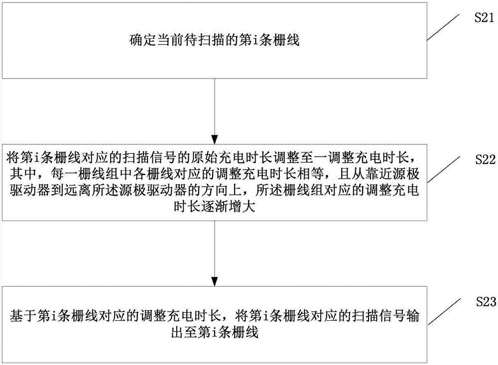
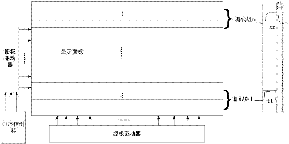
The invention provides a driving method and a driving circuit for a display panel, and a display device. The display panel comprises Y grid lines. According to the scanning sequence of the grid lines, the Y grid lines are divided into multiple grid line groups. Each grid line group comprises at least one grid line. The driving method comprises steps of determining the i-th grid line to be scanned; adjusting the original charging time of the scanning signal corresponding to the i-th grid line to an adjusted charging time, wherein the adjusted charging line corresponding to each grid line in each grid line group is equal, and in a direction gradually away from the source drive, the adjusted charging time corresponding to each grid line group is gradually increased; and based on the adjusted charging time corresponding to the i-th grid line, outputting the scanning signal corresponding to the i-th grid line to the i-th grid line. The charging time corresponding to each grid line is adjusted, the charging rate of the pixel line with the insufficient charging rate is improved, and the charging rate of each line of pixels is enabled to be equal or close.

Description

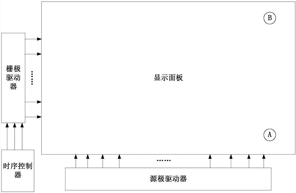
technical field [0001] The invention relates to the field of display technology, and in particular designs a driving method, a driving circuit and a display device of a display panel. Background technique [0002] Such as figure 1 As shown, the liquid crystal display device includes a timing controller (TCON), a source driver (Source Driver), a gate driver (Gate Driver), and a display panel. Wherein, the display panel is provided with vertical data lines (not shown) and horizontal gate lines (not shown), and a pixel array (not shown) located in the pixel area defined by the data lines and the gate lines . The timing controller is used to output the clock signal CPV, the enable signal OE and the frame trigger signal STV to the gate driver, so as to control the gate driver to sequentially charge the corresponding pixel row in the pixel array through the corresponding gate line, so that the source The video data output by the electrode driver is transmitted to the correspond...

Claims


Application Information

Patent Timeline
IPC IPC(8): G09G3/36
CPCG09G3/3677G09G3/3648G09G2310/0213G09G2310/08G09G2310/0251G09G2320/02
Inventor 周留刚汪建明栗首李涛施园
Owner BOE TECH GRP CO LTD
Learn More