Eureka AIR delivers breakthrough ideas for toughest innovation challenges, trusted by R&D personnel around the world.

Display device and driving method thereof

A display device and gate drive technology, which is applied in static indicators, instruments, nonlinear optics, etc., can solve the problems of reducing the charging efficiency of the drive circuit to the pixel array, increasing the difficulty of driving circuit design of the display device, etc., and achieving an improvement Effects of charging efficiency, load difference reduction, and prolonging charging time

Active Publication Date: 2017-06-20
KUSN INFOVISION OPTOELECTRONICS
View PDF6 Cites 9 Cited by
  • Summary
  • Abstract
  • Description
  • Claims
  • Application Information

AI Technical Summary

Problems solved by technology

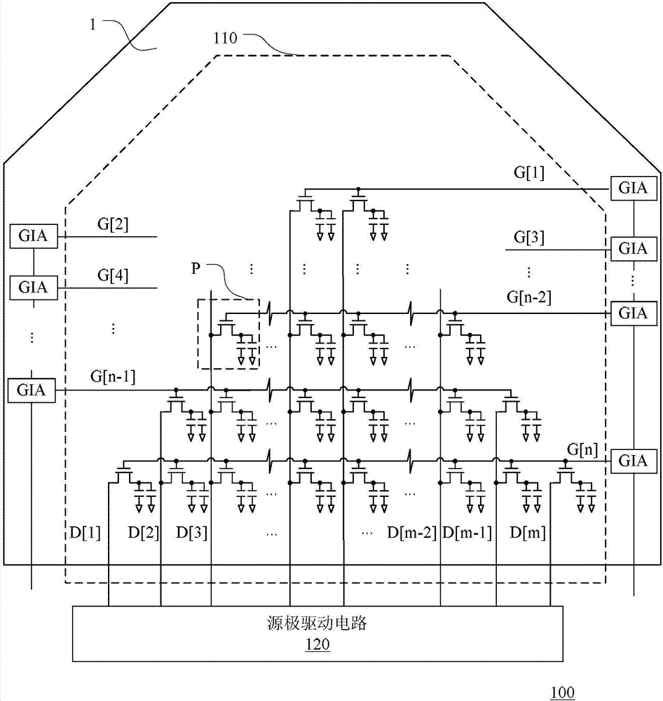
[0004] like figure 1 As shown, in a conventional display device, the gate drive units GIA at all levels apply gate drive signals to each row of pixel units in the pixel array row by row to realize row-by-row scanning, and the source drive circuit 120 is responsible for the gate drive signal The selected pixel unit P applies a corresponding source driving signal to make each pixel unit reach a corresponding gray scale, therefore, the number of pixel units connected to each gate line G[1] to G[n] will appear relatively small. Large differences, the number of pixel units connected to each data line D[1] to D[m] will have a large difference, resulting in a large difference in the load on each gate line and each data line This will affect the quality of the display screen, thereby increasing the difficulty of designing the driving circuit of the display device, and reducing the charging efficiency of the driving circuit to the pixel array.

Method used


Image

  • Display device and driving method thereof
  • Display device and driving method thereof
  • Display device and driving method thereof

Examples


Embodiment Construction

[0023] Hereinafter, the present invention will be described in more detail with reference to the accompanying drawings. In the various figures, identical elements are indicated with similar reference numerals. For the sake of clarity, various parts in the drawings have not been drawn to scale. Also, some well-known parts may not be shown in the drawings.

[0024] In the following, many specific details of the present invention are described, such as device structures, materials, dimensions, processing techniques and techniques, for a clearer understanding of the present invention. However, the invention may be practiced without these specific details, as will be understood by those skilled in the art.

[0025] Hereinafter, the present invention will be described in detail with reference to the accompanying drawings.

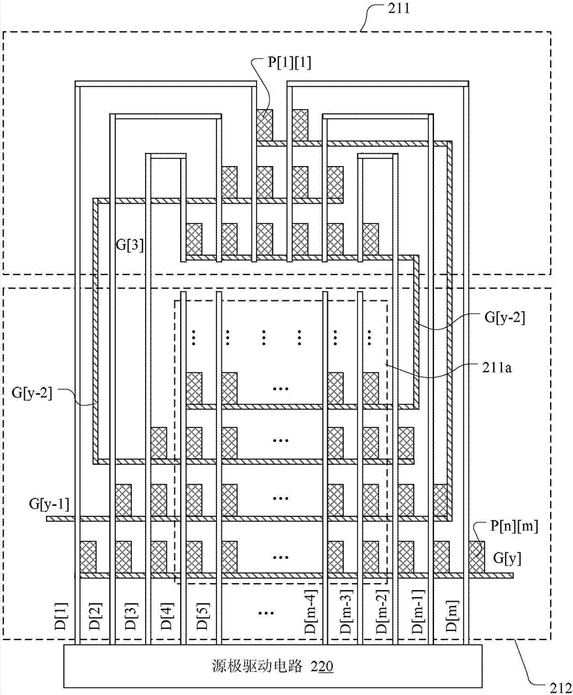
[0026] figure 2 A schematic structural diagram of a display device according to a first embodiment of the present invention is shown.

[0027] Such as fi...


PUM


Abstract

The invention discloses a display device and a driving method thereof. The display device comprises a display panel and a driving circuit. The display panel consists of a plurality of gate lines, a plurality of data lines, and a pixel array arranged by a plurality of pixel units, each pixel unit is connected with one of a plurality of gate lines to receive gate drive signals, each pixel unit is connected with one of a plurality of data lines to receive source driving signals; the driving circuit is used for supplying the gate driving signals to a plurality of gate lines respectively and supplying the source driving signals to a plurality of data lines respectively, wherein at least one of a plurality of gate lines is connected with at least two rows of pixel units in the pixel array and the data lines connected with the pixel units which are connected with the same gate line are different. Compare with the traditional display device, the display device reduces the number of the gate lines, thereby simplifying the design of the wiring and the driving circuit, which is advantageous for achieving the narrow bounding and improving the charging efficiency at the same time.

Description

technical field [0001] The present invention relates to the field of display technology, and more particularly, to a display device and a driving method thereof. Background technique [0002] In recent years, with the popularization of display devices represented by liquid crystal display devices, the uses of display devices have also been gradually diversified. For example, a liquid crystal display device is used in an automobile instead of a conventional instrument panel (instrument panel). Therefore, in addition to designing the display area of ​​the display device as a traditional rectangle, in some cases it is also necessary to design the display area in a variety of shapes according to different applications, such as trapezoidal, circular, or polygonal above pentagonal. [0003] figure 1 A schematic structural diagram of a conventional display device is shown. Such as figure 1 As shown, the display device 100 includes a display panel 110 and a driving circuit, wher...

Claims


Application Information

Patent Timeline
Patent Type & Authority Applications(China)
IPC IPC(8): G02F1/1362G02F1/133G09G3/36
CPCG02F1/13306G02F1/136286G09G3/3648
Inventor 付佃力郑会龙
Owner KUSN INFOVISION OPTOELECTRONICS
Why Eureka
Eureka Blog
Learn More