Light source module and lighting device comprising same
A light source module and blue light technology, applied in lighting devices, components of lighting devices, light sources, etc., can solve the problems of low-price competition and the inability to achieve the light quality of traditional light sources, and achieve high preference and comfort. Effect
- Summary
- Abstract
- Description
- Claims
- Application Information
AI Technical Summary
Problems solved by technology
Method used
Image
Examples
Embodiment 2
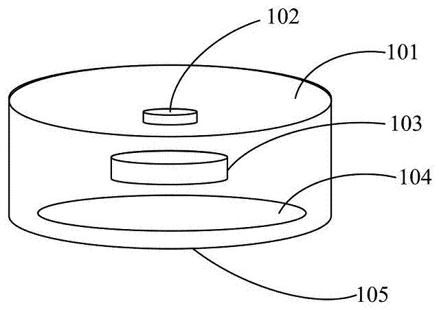
[0070] In Embodiment 2, the light source module 104 is provided with a blue LED chip with a peak wavelength of 450±5nm as the blue light generating part, and a red phosphor that can convert part of the blue light emitted by the blue light generating part into red light is used as the red light generating part , And a green phosphor that can convert part of the blue light emitted by the blue light generating part into green light as the green light generating part. In this embodiment, the blue LED chip serves as the blue light generating part and the excitation light source for the red light generating part and the green light generating part. Figure 4 For the relative spectral energy distribution diagram of Example 2, the blue light energy emitted by the blue LED chip forms the first peak in the figure with a light emission peak wavelength of 450 nm, and a half-width FWHM of 21.8±5 nm. The green phosphor converts part of the blue light emitted by the blue LED chip into green li...
Embodiment 3
[0071] In Embodiment 3, a blue LED chip with a peak wavelength of 450±5nm is provided on the light source module 104 as the blue light generating part, and a red phosphor that can convert part of the blue light emitted by the blue light generating part into red light is used as the red light generating part , And a green phosphor that can convert part of the blue light emitted by the blue light generating part into green light as the green light generating part. In this embodiment, the blue LED chip serves as the blue light generating part and the excitation light source for the red light generating part and the green light generating part. Image 6 For the relative spectral energy distribution diagram of Example 3, the blue light energy emitted by the blue LED chip forms the first peak in the figure with a light emission peak wavelength of 450 nm, and a half-width FWHM of 21.8±5 nm. The green phosphor converts part of the blue light emitted by the blue LED chip into green light...
Embodiment 4
[0072] In Embodiment 4, a blue LED chip with a peak wavelength of 445±5nm is provided on the light source module 104 as the blue light generating part, and a red phosphor that can convert part of the blue light emitted by the blue light generating part into red light is used as the red light generating part , And a green phosphor that can convert part of the blue light emitted by the blue light generating part into green light as the green light generating part. In this embodiment, the blue LED chip serves as the blue light generating part and the excitation light source for the red light generating part and the green light generating part. Figure 8 For the relative spectral energy distribution diagram of Example 4, the blue light energy emitted by the blue LED chip forms the first peak in the figure with a peak wavelength of 445 nm, and a half-width FWHM of 21.4±5 nm. The green phosphor converts part of the blue light emitted by the blue LED chip into green light to form a sec...
PUM
 Abstract
Description
Claims
Application Information
 - R&D
- Intellectual Property
- Life Sciences
- Materials
- Tech Scout
- Unparalleled Data Quality
- Higher Quality Content
- 60% Fewer Hallucinations
Browse by: Latest US Patents, China's latest patents, Technical Efficacy Thesaurus, Application Domain, Technology Topic, Popular Technical Reports.
© 2025 PatSnap. All rights reserved.Legal|Privacy policy|Modern Slavery Act Transparency Statement|Sitemap|About US| Contact US: help@patsnap.com


