A sponge compressor

A compressor and sponge technology, applied in the field of sponge compression processing, can solve the problem of not being able to continuously compress the sponge into 3-5mm, and achieve the scientific and reasonable effect of the technical solution

Active Publication Date: 2018-08-14
青岛三山碳素有限公司
View PDF5 Cites 0 Cited by
  • Summary
  • Abstract
  • Description
  • Claims
  • Application Information

AI Technical Summary

Problems solved by technology

But the prior art does not have ready-made compressed sponges that meet the requirements. If it is made to order, the existing equipment for compressing sponges can only be compressed into sheets and blocks, and tens of meters such as 50 meters long and 3-5cm thick sponges cannot be compressed. Continuously compressed into 3-5mm rolls for flexible cutting
There is no such sponge compression processing equipment in the prior art, which is a blank

Method used


Image

  • A sponge compressor
  • A sponge compressor

Examples


Embodiment Construction

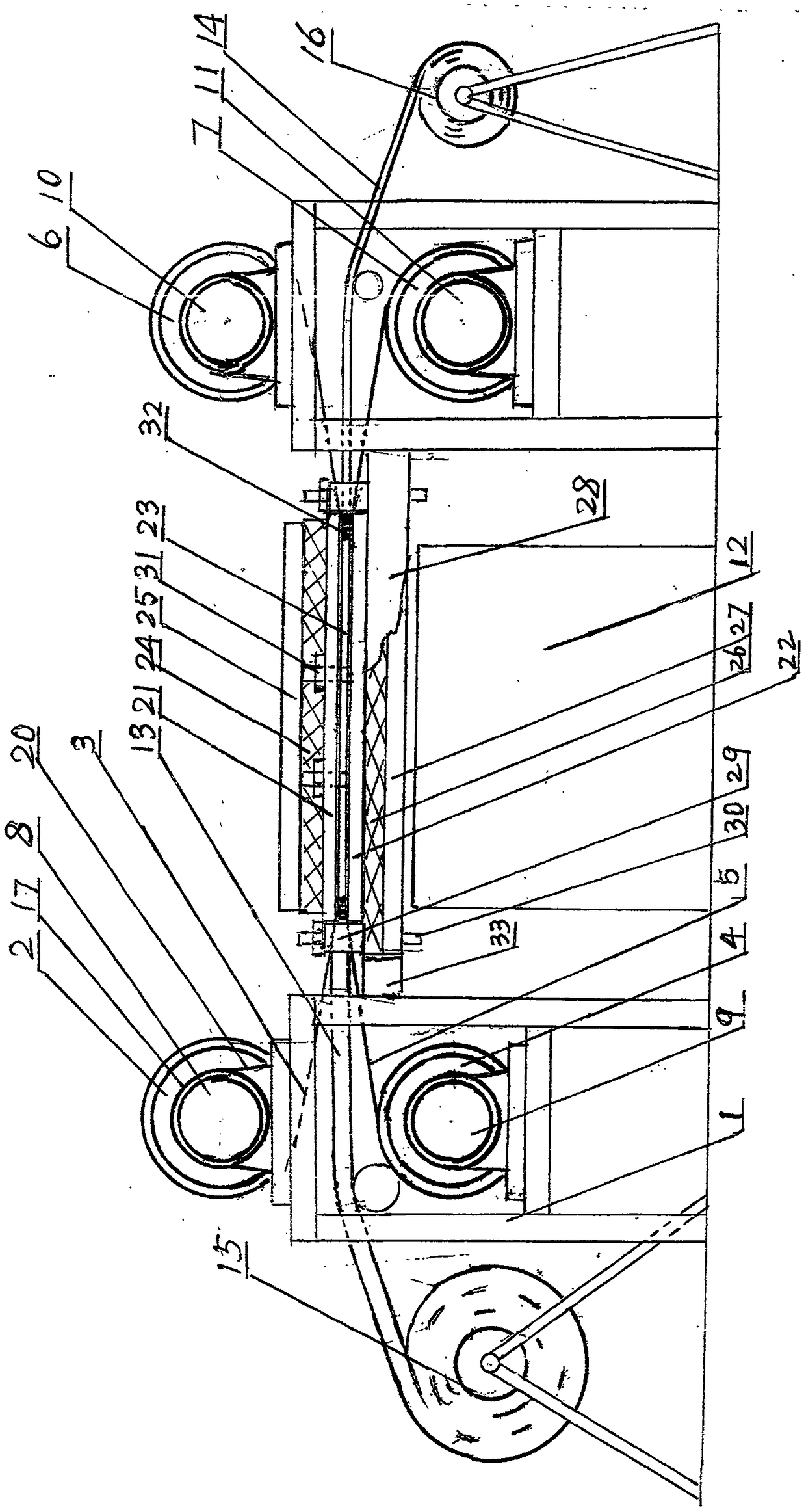
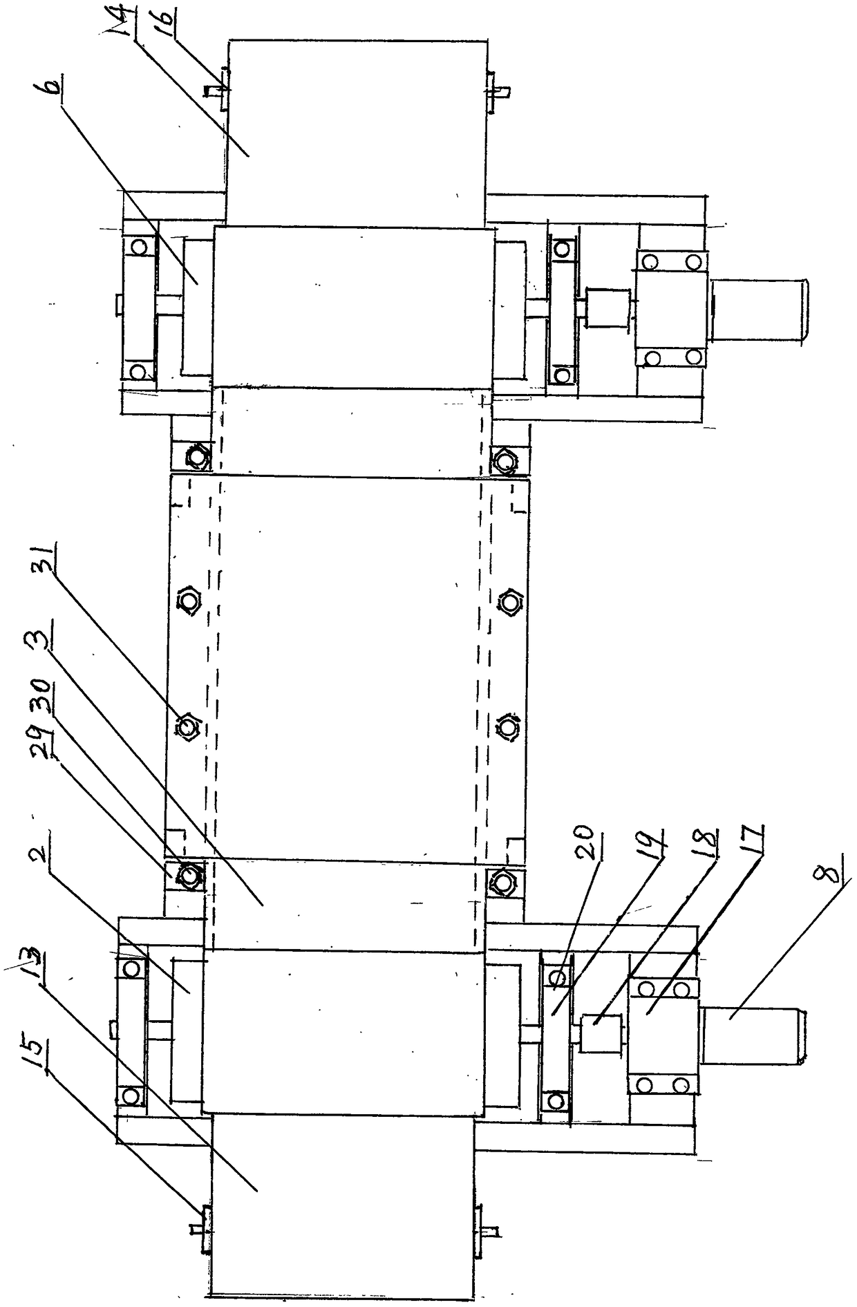
[0012] The accompanying drawings of the description show a specific embodiment of the present invention.

[0013] A sponge compressor comprises a frame 1, a sponge 13 before compression, a sponge 14 after compression, a sponge conveying and moving device, and a sponge heating and compressing device. The sponge conveying mobile device includes a sponge unwinding shaft 15 before compression, a sponge roll unwinding shaft 16 after compression, the first unwinding roller 2 installed on the top of the left frame, and the upper conveying entrainment belt 3 rolled on the first unwinding roller 2 , The second unwinding roller 4 installed on the lower part of the left frame, the lower conveying entrainment belt 5 rolls on the second unwinding roller 4, the first unwinding roller 6 installed on the upper part of the right frame, and the upper conveying entrainment belt 3 rolled on the second A roll puts on the roller 6, is installed in the second roll of the right frame bottom and puts ...


PUM


Abstract

The invention discloses a sponge compressor, and relates to the technical equipment of sponge compression machining. According to the sponge compressor, an upper unwinding roller and a lower unwinding roller are installed on a left rack, an upper winding roller and a lower winding roller are installed on a right rack, the two ends of an upper conveying clamping belt are fixed to the left unwinding roller on the upper portion of the left rack and the right winding roller on the upper portion of the right rack correspondingly, and the two ends of a lower conveying clamping belt are fixed to the left unwinding roller on the lower portion of the left rack and the right winding roller on the lower portion of the right rack correspondingly. An upper hot pressing plate and a lower hot pressing plate are arranged between the left rollers and the right rollers, and a conveying clamping belt and compression sponge clamped and conveyed through the conveying clamping belt run between the upper hot pressing plate and the lower hot pressing plate. The four left and right rollers are each provided with a frequency conversion motor. The motors are controlled by a controller, and the temperature of the hot pressing plates is controlled through a temperature controller. The sponge compressor has the beneficial effects that mechanical and electric combination is achieved, fixed-length sponge is continuously compressed, left-and-right position exchange is achieved, and motor reversing running is achieved; all frequency conversion motors are subject to frequency modulation control, the tension balance of the up-and-down conveying clamping belt can be effectively controlled, and the best movement linear velocity is controlled; the constant-temperature controller is arranged, so that the temperature between the upper hot pressing plate and the lower hot pressing plate is constant and adjustable; and the hot pressing plates are adjustable in vertical movement, and the distance between the two plates is adjustable.

Description

Technical field: [0001] The invention relates to sponge compression processing technology, and mainly relates to sponge compression technology equipment for compressing thick sponges into thin sponges. Background technique: [0002] Sponge is a kind of porous material, mostly made of foamed polymer resin, and the finished product is made of polymers with different densities to synthesize sponges. Although there are product sponge raw materials with different thicknesses and densities, they still cannot meet the needs of some industries. For example, the grinding pad used for sanding machinery to press the abrasive belt, use it to press the back of the abrasive belt, press the front side of the abrasive belt to the workpiece to be processed, and polish the workpiece through the rapid movement of the abrasive belt. The grinding pad used in this sanding machine is composed of a base plate, an elastic buffer pad and a lubricating graphite cloth. The abrasive belt is in better ...

Claims


Application Information

Patent Timeline
Patent Type & Authority Patents(China)
IPC IPC(8): B29C43/24B29C43/44B29C43/32B29C43/52
CPCB29C43/24B29C43/32B29C43/44B29C43/52
Inventor 窦建森王刚
Owner 青岛三山碳素有限公司
Why Eureka
Try Eureka