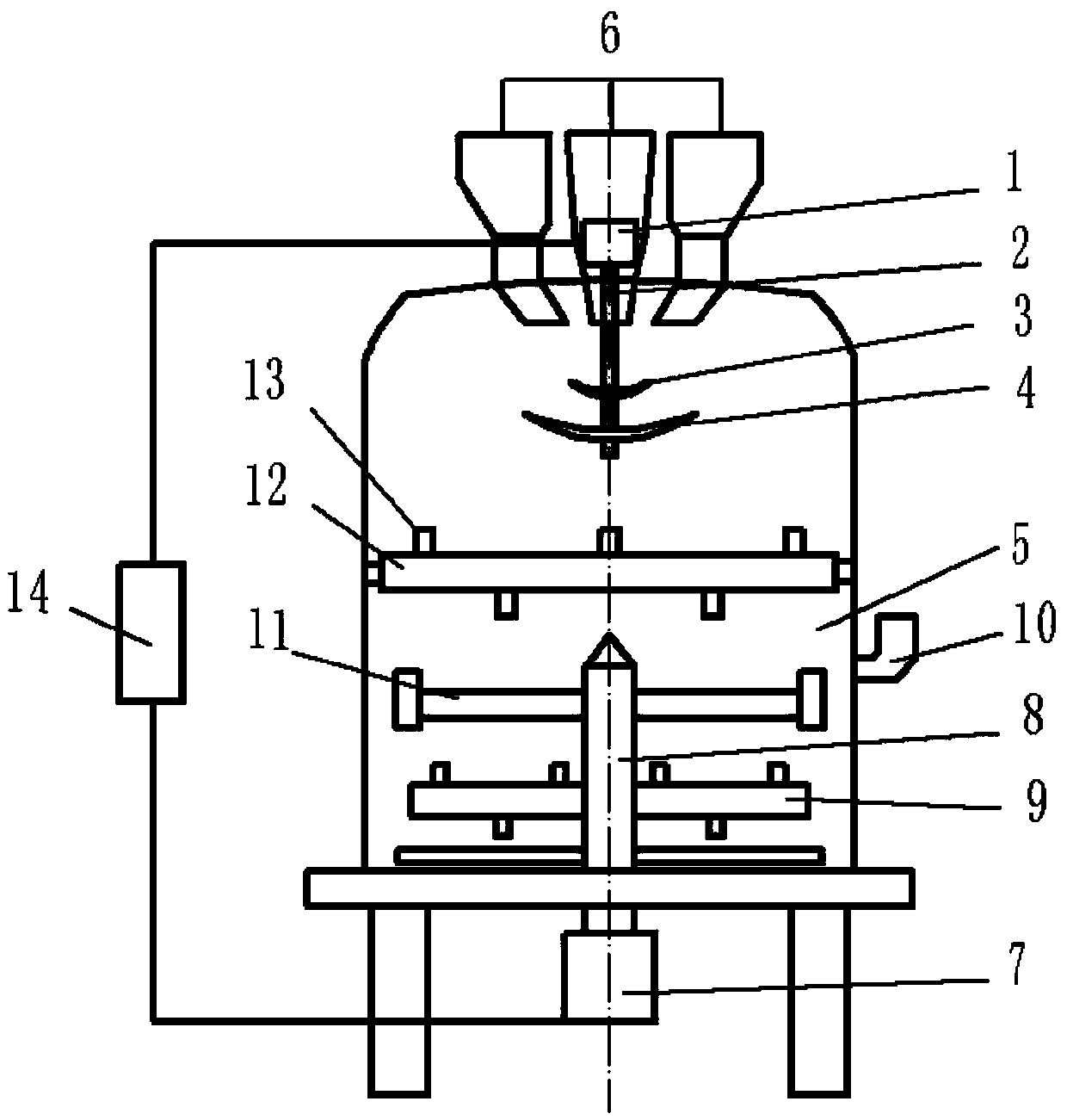
A multi-stage primary mixing disc for mixing equipment
A kind of equipment and mixing technology, applied in the direction of casting molding equipment, metal processing equipment, manufacturing tools, etc., can solve the problems of low mechanical efficiency, achieve the effect of reducing work burden, improving mixing effect, and improving mixing efficiency
- Summary
- Abstract
- Description
- Claims
- Application Information
AI Technical Summary
Problems solved by technology
Method used
Image
Examples
Embodiment 1
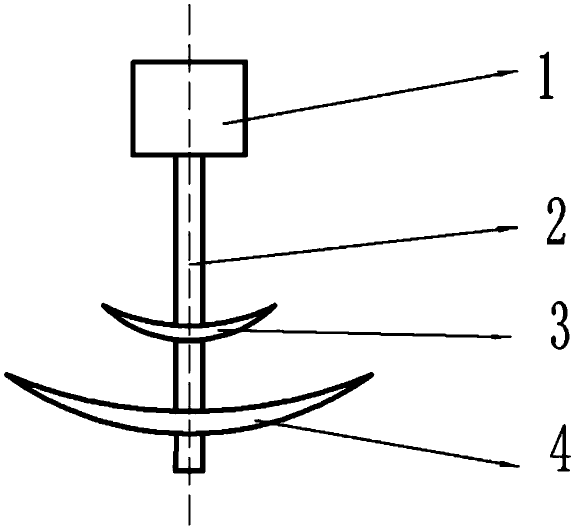
[0030] Such as figure 1 As shown, this embodiment is a two-stage primary mixing disk, including a primary mixing drive mechanism 1, a primary mixing transmission shaft 2, and a first-stage rotating disk 3 and a second-stage rotating disk installed on the same primary mixing transmission shaft for synchronous control. 4. In this embodiment, the shape of the rotating disk is circular, and the upper surface of the cross section of each rotating disk is a concave curved surface structure that smoothly transitions from the outer circumference to the center, that is, the whole rotating disk is a concave disk. The diameter R1 at the outer edge of the stage rotating disk 3 is preferably 35-70% of the diameter R2 at the outer edge of the second stage rotating disk 4, preferably slightly higher than 50%, for example, 55%.
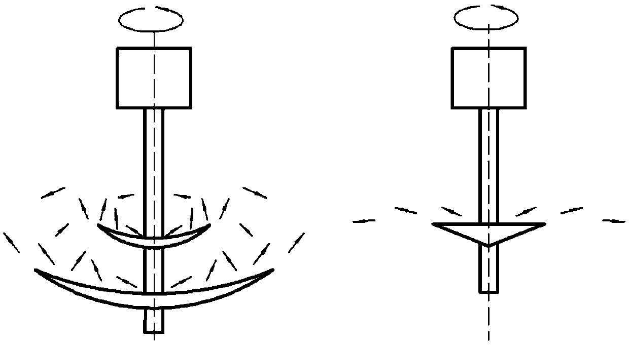
[0031] Such as figure 2 As shown, the left is the working state of the two-stage primary mixing disk of this embodiment, and the right is the working state of the tradi...
Embodiment 2
[0040] As an improvement to the primary mixing disc of the present invention, in this embodiment, two or more first-stage rotating discs 3 at the same level can be provided, and each first-stage rotating disc 3 is different from the second-stage rotating disc 4 Speed and steering movement, such as Figure 4 As shown, the transmission connection can be realized in the following ways: the original mixed transmission shaft is divided into a driving transmission shaft and several driven transmission shafts, and each first-stage rotating disk 3 has its own independent driven transmission shaft, and the shaft end The driven gear 15 is connected, and the end of the driving transmission shaft of the second-stage rotating disk 4 is connected to the driving gear 16. The driving transmission shaft drives the driving gear 16 to rotate under the driving of the primary mixing driving mechanism 1, and the driving gear 16 drives the driven gear 15 to rotate , The driven gear 15 drives the dri...
Embodiment 3
[0043] Different from Embodiment 2, as an improvement to the initial mixing disc of the present invention, in this embodiment, the first-stage rotating disc 3 and the second-stage rotating disc 4 can be controlled at different speeds without adding a new axis position. Such as Figure 5 As shown, the transmission connection can be realized in the following ways: the original mixed transmission shaft is divided into the active transmission inner shaft and the driven transmission outer shaft, the second-stage rotating disc 4 is connected to the active transmission inner shaft, and the first-stage rotating disc 3 is connected to the driven Transmission outer shaft, the shaft end of the active transmission inner shaft is connected to the driving gear 16, and the shaft end of the driven transmission outer shaft is connected to the ring gear 17. The driving inner shaft drives the driving gear 16 to rotate under the driving of the primary mixing drive mechanism 1, and the driving gear ...
PUM
 Abstract
Description
Claims
Application Information
 - R&D
- Intellectual Property
- Life Sciences
- Materials
- Tech Scout
- Unparalleled Data Quality
- Higher Quality Content
- 60% Fewer Hallucinations
Browse by: Latest US Patents, China's latest patents, Technical Efficacy Thesaurus, Application Domain, Technology Topic, Popular Technical Reports.
© 2025 PatSnap. All rights reserved.Legal|Privacy policy|Modern Slavery Act Transparency Statement|Sitemap|About US| Contact US: help@patsnap.com


