
Method for acquiring dynamic vibration frequency

A vibration frequency and dynamic technology, which is applied in the direction of measuring vibration, vibration measurement in solids, using sound waves/ultrasonic waves/infrasonic waves to analyze solids, etc., can solve the problem of not revealing the design method of multiple vibration measurement components

Active Publication Date: 2017-06-16
METAL INDS RES & DEV CENT
View PDF14 Cites 0 Cited by
  • Summary
  • Abstract
  • Description
  • Claims
  • Application Information

AI Technical Summary

Problems solved by technology

[0005] However, the above patent documents do not disclose the design method of symmetrically arranging multiple vibration measuring components on both sides of a spindle, which can directly remove the noise of environmental interference, and quickly obtain dynamic vibration frequency and modal information during cutting

Method used


Image

  • Method for acquiring dynamic vibration frequency
  • Method for acquiring dynamic vibration frequency
  • Method for acquiring dynamic vibration frequency

Examples


Embodiment Construction

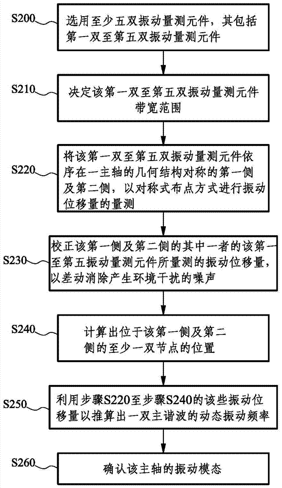
[0027] Please refer to figure 1 , which shows a method for capturing a dynamic vibration frequency according to an embodiment of the present invention, including the following steps:

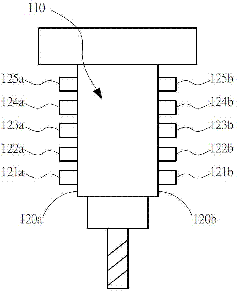
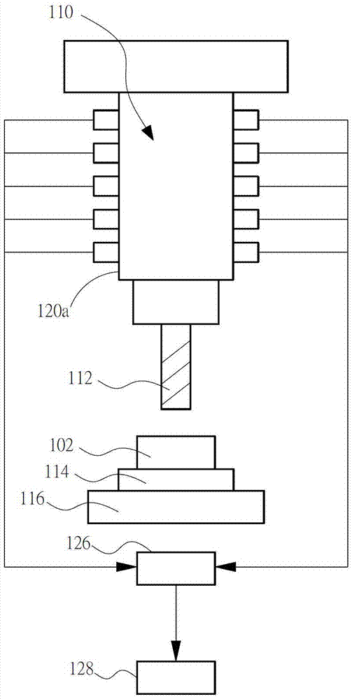
[0028] In step S200, at least five pairs of vibration measuring elements are selected, including first to fifth pairs of vibration measuring elements. Please refer to Figure 2a , which shows the first to fifth dual vibration measuring elements according to an embodiment of the present invention. The first dual vibration measuring elements 121a, 121b include two first vibration measuring elements 121a, 121b, the second dual vibration measuring elements 122a, 122b include two second vibration measuring elements 122a, 122b, and accordingly By analogy, the vibration measuring element can be a vibration accelerometer for measuring a vibration displacement. Please refer to Figure 2a and Figure 2b , a measuring system comprising the first pair to the fifth pair of vibration measuring elements, ...


PUM


Abstract

A method for acquiring a dynamic vibration frequency is disclosed, which includes the following steps. At least five pairs of vibration measurement elements are selected. A bandwidth range of the first to fifth pairs of vibration measurement elements is determined. The first to fifth pairs of vibration measurement elements in sequence on a first side and a second side, which are geometrically symmetrical to each other, of a main shaft are used to measure vibration displacements in a symmetrical position arranging manner. The vibration displacements measured by the first to fifth pairs of vibration measurement elements of either of the first side and second side are corrected, so as to differentially eliminate an ambient noise. Positions of at least one pair of nodes located on the first side and the second side are calculated. The vibration displacements in the preceding steps are used to deduce dynamic vibration frequencies of one pair of main harmonics. A vibration mode of the main shaft is confirmed. The method of the invention can be used for quickly measuring the dynamic vibration frequencies during the cutting process and for gain a clear understanding of the cutting dynamic vibration frequencies, modes, and node positions.

Description

technical field [0001] The present invention relates to a method for capturing dynamic vibration frequency, in particular to a method for capturing dynamic vibration frequency during cutting. Background technique [0002] The market demand for micro-milling processing has increased rapidly, and the focus of industrial competition has been towards intelligent development. The most important link is real-time cutting vibration monitoring, which can be used to understand the operation status of the spindle and control the yield rate of equipment. However, the unit price of the high-precision cutting vibration sensing device currently available on the market is relatively high, and the feasibility of introducing it is not good. [0003] The main function of on-line chatter avoidance is to protect cutting machine tools. Through the micro-vibration sensing element installed in the machining area of ​​the cutting tool (such as the sheet metal of the spindle), the analysis software...

Claims


Application Information

Patent Timeline
Patent Type & Authority Applications(China)
IPC IPC(8): G01H17/00
CPCG01N29/12G01H1/003G01H1/006G01N29/4463G01N2291/014G01N2291/105G01H17/00
Inventor 詹家铭吴文杰
Owner METAL INDS RES & DEV CENT
Learn More