
Horn and earplug earphone

A speaker and earphone technology, which is applied in ventilated earplugs, earpiece/earphone accessories, earphone manufacturing/assembly, etc. It can solve the problems of increased pressure in the rear acoustic cavity, weakened vibration force of the diaphragm, and bulky products, so as to improve the bass effect and enhance the Effect of improving vibration performance and acoustic performance

Active Publication Date: 2017-06-13
GEER TECH CO LTD
View PDF6 Cites 12 Cited by
  • Summary
  • Abstract
  • Description
  • Claims
  • Application Information

AI Technical Summary

Problems solved by technology

[0003] At present, the earphones with waterproof function adopt the following technologies: the existing tuning technology, that is, the design of the sound leakage hole for the rear sound cavity of the speaker to expand the low frequency, the sound leakage hole needs to be unobstructed and have a high air flow; but due to the IPX7 waterproof The air permeability of the materials is very low, and they are basically airtight, which cannot meet the two conditions required by the sound leakage hole: one is unobstructed, and the other is high air permeability, resulting in poor low-frequency effects.
If the low-frequency effect is improved only by increasing the volume of the rear acoustic cavity, the volume of the product will increase, making the product appear bulky and destroying the aesthetics of the product
During the working process of the closed rear acoustic cavity, that is, when the diaphragm vibrates, the diaphragm will compress the volume of the rear acoustic cavity, causing the internal pressure of the rear acoustic cavity to increase, and the reaction force to the diaphragm, thus weakening the vibration force of the diaphragm, resulting in failure Unleashes a strong enough bass effect

Method used


Image

  • Horn and earplug earphone
  • Horn and earplug earphone
  • Horn and earplug earphone

Examples


Embodiment Construction

[0020] In order to make the object, technical solution and advantages of the present invention clearer, the present invention will be further described in detail below in conjunction with the accompanying drawings and embodiments. It should be understood that the specific embodiments described here are only used to explain the present invention, not to limit the present invention.

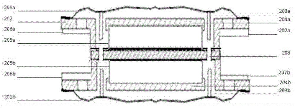
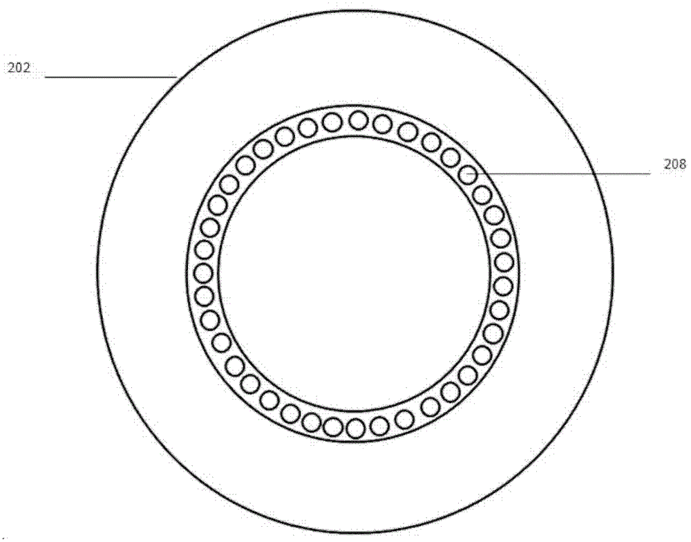
[0021] Depend on figure 1 and figure 2 It can be seen that the horn includes a horn bracket 202, and the horn bracket 202 includes a cylindrical horn housing, and a partition plate arranged radially is arranged in the cavity surrounded by the horn housing, and the partition plate divides the horn housing The enclosed cavity is divided into two parts; a first horn 105a and a second horn 105b are respectively arranged on both sides of the partition plate, and the first horn 105a and the second horn 105b respectively include magnetic components fixed on the partition plate. The magnetic circuit sys...


PUM


Abstract

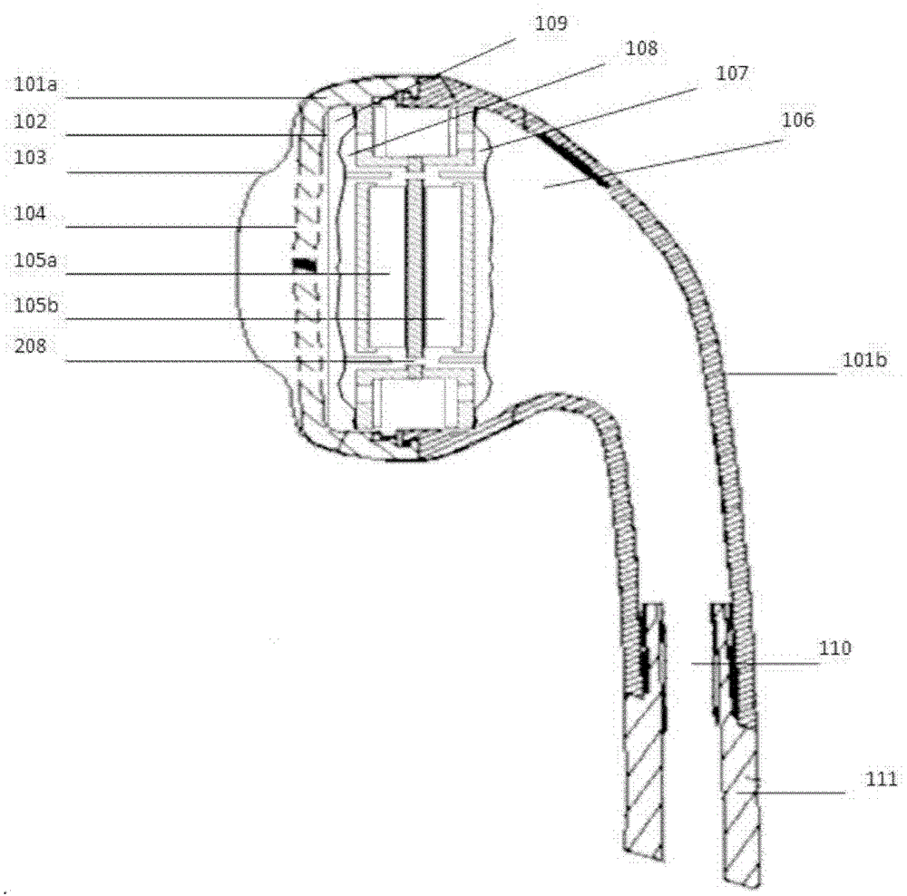
The invention belongs to the technical field of earphones, and particularly relates to a horn and an earplug earphone. The horn comprises a cylindrical horn shell, a partition board arranged along the radial direction is deployed in an enclosed cavity, a first horn and a second horn are respectively arranged on both sides of the partition board, and each horn comprises a magnetic circuit system and a vibration system; a magnetic gap is arranged between the magnetic circuit system and the horn shell, and an air pressure balance hole is formed in the partition board located at the magnetic gap; the vibration system comprises a voice coil and a vibrating diaphragm covered on the end part of the horn shell, and the voice coil is fixedly connected with a side face of the vibrating diaphragm; and the earplug earphone comprises an earphone front shell and an earphone back shell, which are buckled together, the horns are installed in the enclosed space, a plurality of front shell sound outlet holes are formed in the earphone front shell, and an acoustic waterproof membrane is arranged between the plurality of front shell sound outlet holes and the horns. As the vibration directions of the vibrating diaphragms of the two horns are the same, the vibration performance is enhanced and the bass effect is improved, due to the acoustic waterproof membrane, no sound release hole is formed, and the waterproof performance is enhanced.

Description

technical field [0001] The invention belongs to the technical field of earphones, in particular to a loudspeaker and earplug earphones. Background technique [0002] With the rapid development of science and technology, people have higher and higher requirements for the quality of life, and consumer electronic products are developing towards high quality. This trend is especially obvious in the research and development and production of earphones. Like many current brands of mobile phones, they are also developing towards waterproof function, not only limited to earphones that can realize waterproof function, but also hope to further improve the sound quality effect on the premise of meeting the waterproof function. [0003] At present, the earphones with waterproof function adopt the following technologies: the existing tuning technology, that is, the design of the sound leakage hole for the rear sound cavity of the speaker to expand the low frequency, the sound leakage hol...

Claims


Application Information

Patent Timeline
IPC IPC(8): H04R1/10
CPCH04R1/1091H04R2201/10H04R1/1016H04R1/1075H04R1/2826H04R9/025H04R9/045H04R2400/11H04R2460/11H04R9/06
Inventor 王承谦
Owner GEER TECH CO LTD
Learn More