A method and system for comprehensively locating faults in transmission lines

A transmission line and positioning system technology, applied in the field of power systems, can solve problems such as inconvenient operation and maintenance of lines, difficulty in starting devices, and poorer stability than substations, etc., to solve the problem of inability to diagnose high-resistance faults and reduce the impact of attenuation and distortion , Solve the effect of unknown fault interval

Active Publication Date: 2019-12-24
WUHAN SUNSHINE POWER SCI & TECH
View PDF5 Cites 0 Cited by
  • Summary
  • Abstract
  • Description
  • Claims
  • Application Information

AI Technical Summary

Problems solved by technology

Traveling wave ranging devices currently used in transmission line fault diagnosis include traditional traveling wave ranging devices for substations and distributed traveling wave ranging devices for transmission lines that have emerged in recent years. Among them, traveling wave ranging devices for substations are stable and can diagnose large Some metal grounding and lightning strike faults, but for some high-resistance faults, the device is difficult to start. In addition, the positioning error of the device is relatively large. For cross-area lines, when the fault occurs near the demarcation point, it is impossible to judge the section to which the fault belongs. Line operation and maintenance bring great inconvenience
Distributed traveling wave distance measuring device has a large investment and is not as stable as substation traveling wave distance measuring device, but it can theoretically solve the problems of high resistance grounding and positioning accuracy

Method used


Image

  • A method and system for comprehensively locating faults in transmission lines
  • A method and system for comprehensively locating faults in transmission lines
  • A method and system for comprehensively locating faults in transmission lines

Examples


Embodiment Construction

[0023] The technical solutions of the present invention will be further described below in conjunction with the accompanying drawings and specific embodiments.

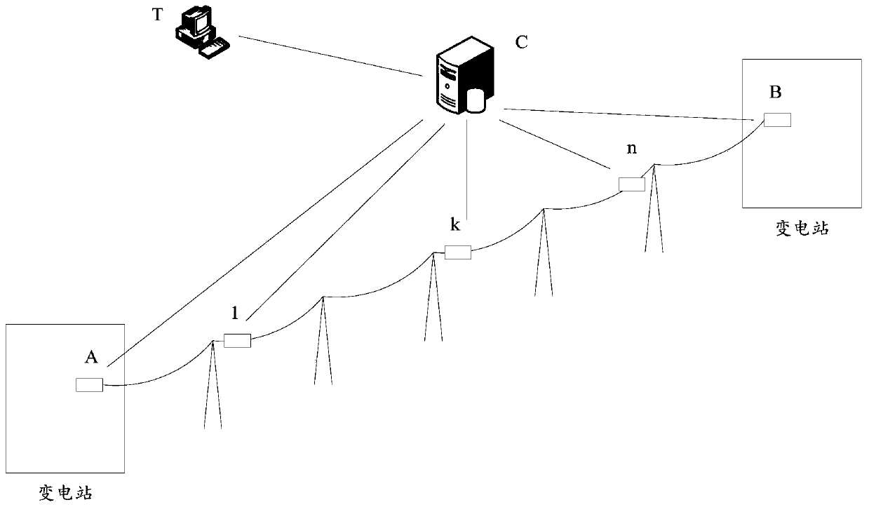
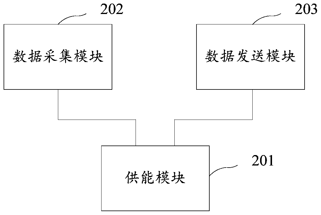
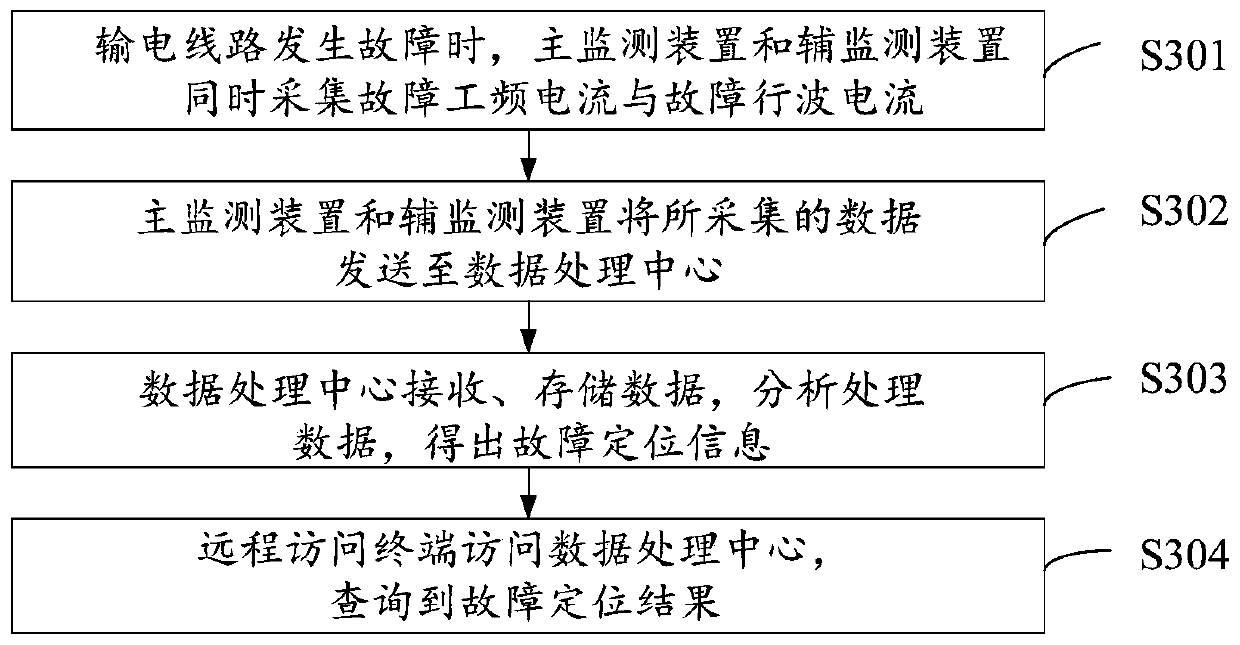
[0024] figure 1 Shown is a schematic structural diagram of a transmission line fault comprehensive positioning system in an embodiment of the present invention, the system includes: main acquisition devices A, B, auxiliary acquisition devices 1, ..., k, ..., n, data processing center C , remote access terminal T.

[0025] The main acquisition devices A and B are installed in the substations at both ends of the transmission line; the auxiliary acquisition devices 1, ..., k, ..., n are installed on the transmission line, and the installation location and installation of the auxiliary acquisition devices can be flexibly selected as required. The number of auxiliary acquisition devices should be increased in the fault-prone sections of long lines, especially at the boundary points of cross-district transmission lines or ...


PUM


Abstract

The invention provides a power-transmission-line-fault comprehensive positioning method and system. The power-transmission-line-fault comprehensive positioning method includes the steps that when a power transmission line faults, a primary monitoring device and a secondary monitoring device collect fault power frequency currents and fault traveling wave currents at the same time; the primary monitoring device and the secondary monitoring device send the collected data to a data processing center; the data processing center receives and stores the data, and analyzes and processes the data, and fault positioning information is obtained; a remote access terminal accesses the data processing center, and the fault positioning result is queried. According to the power-transmission-line-fault comprehensive positioning method and system, accurate positioning of a fault is achieved, the problems that a high-resistance fault cannot be judged with a traditional transformer-substation travelling wave fault location method, and fault intervals are unknown are solved, and the power-transmission-line-fault processing efficiency and the working reliability are greatly improved.

Description

technical field [0001] The invention relates to the field of power systems, in particular to a method and system for comprehensive fault location of transmission lines. Background technique [0002] Modernization has higher and higher requirements on the quality of power grid operation. Electric power workers need to keep abreast of the operation of power equipment and analyze the causes of faults. Therefore, it is very important to record various faults that occur during the operation of the power grid in real time, completely and accurately. necessary. [0003] In recent years, the fault location technology based on the principle of traveling wave ranging has been widely used in the application of transmission line fault diagnosis, which has greatly improved the efficiency of transmission line fault diagnosis and greatly reduced the national economic losses caused by power outages. Traveling wave ranging devices currently used in transmission line fault diagnosis include ...

Claims


Application Information

Patent Timeline
Patent Type & Authority Patents(China)
IPC IPC(8): G01R31/08
CPCG01R31/085Y04S10/52
Inventor 钱冠军樊宇航胡枫余刚华赵纯谈发力
Owner WUHAN SUNSHINE POWER SCI & TECH
Why Eureka
Try Eureka