


Quick Research
Generate reliable direction feasibility study reports for your R&D in just a few steps.

Technical Q&A
Discover and master advanced knowledge NOW. Basics, ideas, possibilities, all at once.

Find Solutions
As an expert in R&D theories, this can generate solutions to your technical problems instantly.

Evaluate Feasibility
Analyze your overall solution with one click, know your potential R&D risks in advance.

Monitor Landscape
Get weekly tech updates, stay abreast of the latest tech innovations and key insights.
Signal-abnormal-assistant positioning circuit and method
An auxiliary positioning and signal abnormality technology, which is applied in the field of signal processing, can solve problems such as analysis and debugging work resistance, inability to locate signal signal status, and inability to restore abnormal status, so as to improve debugging and verification efficiency and reduce development costs.
- Summary
- Abstract
- Description
- Claims
- Application Information
AI Technical Summary
Problems solved by technology
Method used
Image

Examples
Embodiment 1
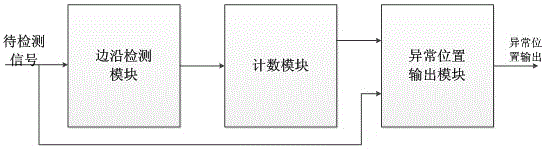
[0025] Configure signal abnormality auxiliary positioning circuit, the auxiliary positioning circuit is mainly composed of counting module, edge detection module and abnormal position output module;
[0026] The counting module counts the clock cycle of the signal to be detected, before which the output of the edge detection module is effectively cleared; the count overflow valid signal is sent to the abnormal position output module to determine whether the abnormal position output signal is Effective; the counting range of the counting module is determined by the maximum value of the observed value of the interval between the normal high and low level transitions of the signal to be detected; the effective signal of the counting overflow of the counting module is determined by each bit of the counting module or its logical combination.
[0027] The edge detection module is used to detect the rising edge or falling edge change of the signal to be detected, the change trend of t...
Embodiment 2
[0034] Configure signal abnormality auxiliary positioning circuit, the auxiliary positioning circuit is mainly composed of counting module, edge detection module and abnormal position output module;
[0035] The counting module is effectively cleared by the output of the edge detection module, counts the clock cycle of the signal to be detected, and determines a count overflow upper limit by observing and analyzing the waveform of the signal to be detected, using the upper three bits of the counter or its logical combination As counting overflow effective output, its counting overflow effective signal is sent into described abnormal position output module, is used for judging whether the abnormal position output signal is effective; Described counting module counting range is by the interval of normal high and low level transition of signal to be detected The maximum value of the calculated value is determined; the effective signal of counting overflow of the counting module is...
PUM
 Abstract
Description
Claims
Application Information
 - R&D Engineer
- R&D Manager
- IP Professional
- Industry Leading Data Capabilities
- Powerful AI technology
- Patent DNA Extraction
Browse by: Latest US Patents, China's latest patents, Technical Efficacy Thesaurus, Application Domain, Technology Topic, Popular Technical Reports.
© 2024 PatSnap. All rights reserved.Legal|Privacy policy|Modern Slavery Act Transparency Statement|Sitemap|About US| Contact US: help@patsnap.com