Positioning ultrasonic testing device and positioning ultrasonic testing method for plane welding component

A technology of plane welding and ultrasonic testing, which is applied to measuring devices, analyzing solids using sound waves/ultrasonic waves/infrasonic waves, and using sound waves/ultrasonic waves/infrasonic waves for material analysis, etc. It can solve problems such as complex ultrasonic scanning mechanisms and large footprints , to achieve the effect of low processing difficulty, low manufacturing cost and simple structure

Active Publication Date: 2017-06-13
JILIN UNIV
View PDF5 Cites 5 Cited by
  • Summary
  • Abstract
  • Description
  • Claims
  • Application Information

AI Technical Summary

Problems solved by technology

[0003] The object of the present invention is to provide a positioning ultrasonic detection device and method for plane welded parts, which is suitable for the detection of large-scale plane welded parts, solves the problems of complex ultrasonic scanning mechanism and large footprint in the prior art, and realizes Quantitative ultrasonic testing of large-scale weldments, while performing high-precision online quantitative scanning of internal defects of the workpiece, and forming numerical values ​​and images through computer fitting

Method used


Image

  • Positioning ultrasonic testing device and positioning ultrasonic testing method for plane welding component
  • Positioning ultrasonic testing device and positioning ultrasonic testing method for plane welding component
  • Positioning ultrasonic testing device and positioning ultrasonic testing method for plane welding component

Examples


Embodiment Construction

[0038] The details of the present invention and its specific implementation will be further described below in conjunction with the accompanying drawings, taking the detection of honeycomb brazing plate workpieces commonly used in the medical industry as an example.

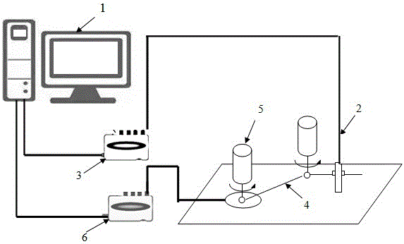
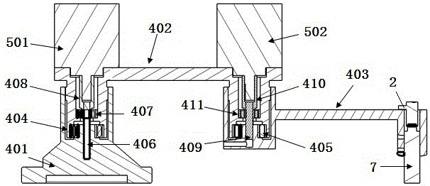
[0039] see figure 1 and figure 2 As shown, the positioning ultrasonic detection device for plane welded parts of the present invention includes an industrial computer 1 , an ultrasonic probe 7 , an ultrasonic detection module 3 , a series robot arm 4 , an angle sensor and a data acquisition card 6 . The ultrasonic probe 7 is connected with the ultrasonic detection module 3 through the probe connection line. The ultrasonic detection module 3 is composed of an ultrasonic pulse transmitting circuit, an ultrasonic receiving circuit and an A / D analog-to-digital conversion circuit. It is connected with the industrial computer 1 through the PCI bus, and the mechanical arm 4 is connected in series. The mechanical arm s...


PUM


Abstract

The invention relates to a positioning ultrasonic testing device and a positioning ultrasonic testing method for a plane welding component and belongs to the field of ultrasonic testing. The structure of the device is as follows: an ultrasonic probe is connected with an ultrasonic testing module through a probe connecting line; the ultrasonic testing module is connected with an industrial computer through a PCI bus; a serial mechanical arm has a mechanical arm structure formed by the connecting rods in serial connection; the ultrasonic probe can realize the plane structure detection; an angle sensor on the serial mechanical arm is used for converting the angle change of each connecting rod into an electric signal and feeding back to a data collecting card; the electric signal is inputted to the industrial computer through a USB connecting line. The method comprises the following steps: treating a workpiece surface and scanning the workpiece surface. The invention has the advantages that the problems of complex ultrasonic scanning mechanism and large floor space can be solved; the quantitative ultrasonic testing of large-size welding component is realized; the high-precision online quantitative scanning is performed on an internal defect of the workpiece and the computer is used for fitting and forming numerical value and image.

Description

technical field [0001] The invention relates to the field of ultrasonic testing, in particular to an ultrasonic testing device and method for positioning a planar welded part based on a tandem mechanical arm. It is suitable for the detection of large-scale flat weldments. Background technique [0002] Quantitative ultrasonic testing usually uses a mechanical mechanism to drive the ultrasonic probe. By controlling the movement of the mechanical mechanism, the ultrasonic probe reaches a specific position and scans in a specific area. At each scanning point, the position information is fed back by the mechanical mechanism, the internal state of the workpiece is fed back by the ultrasonic probe, and then through computer fitting, the defect information of all scanning points inside the workpiece can be obtained. The two-dimensional surface of the workpiece often uses X-Y bidirectional motor to drive the mechanical mechanism and drive the ultrasonic probe to scan the surface of ...

Claims


Application Information

Patent Timeline
IPC IPC(8): G01N29/06G01N29/04G01N29/22G01N1/28G01N1/34
CPCG01N1/28G01N1/34G01N29/048G01N29/069G01N29/22G01N2291/023G01N2291/0234G01N2291/0289G01N2291/102G01N2291/2632
Inventor 徐国成董娟王亭谷晓鹏
Owner JILIN UNIV
Why Eureka
Try Eureka