
Single shear test device considering tensile bar bursting force

A test device and steel bar technology, applied in the direction of measuring device, using stable shear force to test the strength of materials, instruments, etc., can solve the problems of many influencing factors, high test cost, unfavorable failure mechanism, etc., and achieve the goal of reducing the test cost Effect

Inactive Publication Date: 2017-06-13
GUANGDONG UNIV OF TECH
View PDF6 Cites 5 Cited by
  • Summary
  • Abstract
  • Description
  • Claims
  • Application Information

AI Technical Summary

Problems solved by technology

[0004] Existing research on the end-stripping failure of FRP-strengthened reinforced concrete beams is mainly based on the experimental research of FRP-strengthened reinforced concrete beams. There are many factors affecting this type of experiment, which is not conducive to the clarification of the failure mechanism. At the same time, this type of experiment needs to pour the entire reinforced concrete beam. board, the test cost is higher

Method used


Image

  • Single shear test device considering tensile bar bursting force
  • Single shear test device considering tensile bar bursting force
  • Single shear test device considering tensile bar bursting force

Examples


Embodiment 1

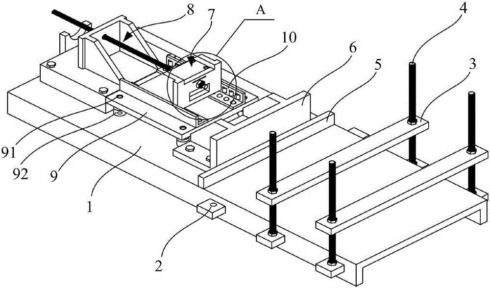
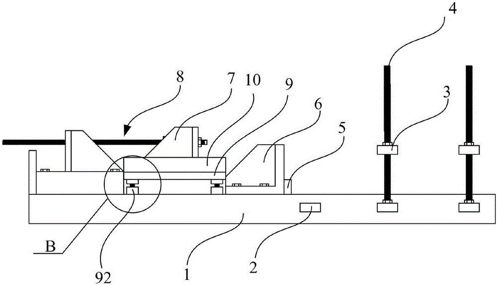
[0035] see figure 1 , the present invention proposes a single shear test device considering the splitting force of the tensioned steel bar. The top surface of the top is vertically connected with the support screw 4. A fixed plate 3 for clamping the test piece and cooperating with the support screw 4 to move up and down is provided above one end of the bottom plate 1 . In this embodiment, a number of fixing seats 2 are fixedly connected to the left and right sides of one end of the bottom plate 1, and the middle part of the fixing seats 2 is provided with a screw hole and is connected with the support screw 4 through thread fit, wherein the support screw 4 is connected to the fixing seat 2 The thread connection is detachable, so when the support screw 4 cooperates with the fixed plate 3 to clamp the test piece, the support screw 4 can be installed on different fixing seats 2, or multiple support screws 4 and multiple fixed plates 3. Cooperate with each other to clamp the tes...

Embodiment 2

[0045] This embodiment is the same as Embodiment 1 except for the following features. The sliding positioning device arranged between the fixture and the bottom plate is a linear guide rail, the fixed guide rail of the linear guide rail is fixedly connected with the top surface of the bottom plate, and the slider of the linear guide rail is fixedly connected with the bottom surface of the fixture .

[0046] Through the setting of the above structure, the fixture can slide linearly on the top surface of the bottom plate through the linear guide rail. At the same time, when the fixture slides along the linear guide rail, the linear guide rail can limit the left and right swing of the fixture, thereby improving the accuracy of sliding. It should be noted that the number of linear guide rails arranged between the fixture and the bottom plate is two, and the two linear guide rails are parallel to each other and arranged near the side of the bottom surface of the fixture, so that th...

Embodiment 3

[0048] This embodiment is the same as Embodiment 1 except the following features: a level is also provided on the leveling plate.

[0049] In this embodiment, by setting the level bar on the leveling plate, it is convenient for the experimental operator to quickly level the leveling plate in place through the movement of the water bubble of the level bar during the experimental operation. Preferably, the level provided on the leveling plate is two water bubbles parallel to the leveling plate and perpendicular to each other. The water bubbles perpendicular to each other can make the leveling of the leveling plate more convenient and fast.


PUM


Abstract

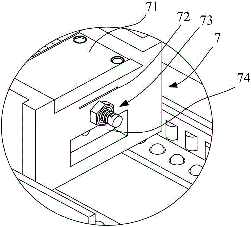
The invention discloses a single shear test device considering tensile bar bursting force. The single shear test device is characterized in that a fixed seat is arranged at one end of a bottom plate; a support screw rod is vertically connected with a fixing plate; the middle part of the top surface of the bottom plate is fixedly connected with a supporting seat; a support base plate is further arranged between the supporting seat and a test piece; the other end of the top surface of the bottom plate is provided with a fixture for clamping a test piece steel bar and an FRP (Fiber Reinforce Plastic) strip; the side face, which faces the test piece, of the fixture is provided with a first through hole through which the FRP strip passes; the upper part of the fixture is further provided with a clamping plate capable of clamping the FRP strip; a second through hole is formed below the first through hole; one end of a long screw rod passes through the second through hole; the other end of the long screw rod is connected with a jack, so that the fixture is under back pulling action force; a third through hole through which the steel bar passes is further formed below the second through hole; the side face, which faces away from the test piece, of the fixture is provided with a flange which is connected with the steel bar through the screw rod and covers the third through hole. By adopting the single shear test device, the bursting force of a tensile bar is considered, so that peeling at the plate end of an FRP reinforced steel bar concrete beam is simulated accurately. The single shear test device has the advantages of simple structure, reliability, convenience in use, low test cost and the like.

Description

technical field [0001] The invention relates to the field of reinforcement of reinforced concrete beam structures, in particular to a simple shear test device considering the splitting force of tensioned steel bars. Background technique [0002] In the prior art, fiber-reinforced composite material (FRP for short) is a new type of high-performance material composed of continuous fiber and resin matrix. In terms of strength, FRP materials are at least twice as high as steel materials, and even up to 10 times. In terms of weight, the weight of FRP materials is one-fifth or even less than that of steel bars with the same volume. In terms of corrosion resistance, the predicted service life of FRP materials in corrosive environments such as seawater can be as long as 100 years or more. Because FRP material has superior properties such as high strength, light weight, and good corrosion resistance, it is widely used in reinforced concrete structure reinforcement projects. [000...

Claims


Application Information

Patent Timeline
Patent Type & Authority Applications(China)
IPC IPC(8): G01N3/24G01N3/02
CPCG01N3/02G01N3/24
Inventor 林煊誉刘锋付兵李丽娟
Owner GUANGDONG UNIV OF TECH
Learn More