
A pressurized leak plugging fixture for blisters on the end face of flange cover and using method

A technology for plugging leakage under pressure and trachoma, which is applied in the direction of pipe components, mechanical equipment, pipes/pipe joints/fittings, etc., to save manufacturing and construction time, seal the cavity small, and reduce the secondary leakage rate.

Active Publication Date: 2019-09-03
天津天石带压密封有限公司
View PDF9 Cites 0 Cited by
  • Summary
  • Abstract
  • Description
  • Claims
  • Application Information

AI Technical Summary

Problems solved by technology

[0005] Aiming at the above-mentioned deficiencies in the prior art, the present invention provides a pressurized leakage plugging fixture for trachoma on the end face of the flange cover and its use method. How to control the deformation of the fixture, reduce the overflow of the sealant in the sealed cavity, and ensure the successful plugging under pressure when it is flammable and explosive and cannot be welded

Method used


Image

  • A pressurized leak plugging fixture for blisters on the end face of flange cover and using method
  • A pressurized leak plugging fixture for blisters on the end face of flange cover and using method
  • A pressurized leak plugging fixture for blisters on the end face of flange cover and using method

Examples


Embodiment Construction

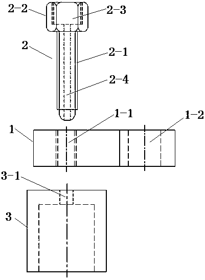
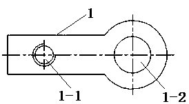
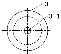
[0021] Such as Figure 1 to Figure 3 As shown in the figure, a leak plugging fixture under pressure for the trachoma on the end face of the flange includes a pressure plate 1 , a top wire 2 and a cover bowl 3 .

[0022] One end of the pressing plate 1 is a rectangular plate, and the other end is a circular plate. A screw hole I1-1 is arranged on the rectangular plate of the pressing plate 1, and a through hole 1-2 is arranged on the circular plate of the pressing plate 1.

[0023] The jackscrew shank at one end of the jackscrew 2 has an external thread 2-1, and the jackscrew cap 2-2 at the other end of the jackscrew 2 is rectangular or polygonal, and a screw hole with an internal thread is provided on the jackscrew 2-2 surface II2-3, an injection channel 2-4 is arranged in the jacking screw, and the screw hole II2-3 communicates with the injection channel 2-4.

[0024] The gaiwan 3 is circular, and the center of the gaiwan 3 faces is provided with an injection channel hole 3-...


PUM


Abstract

The invention relates to a pressurized leakage-stopping clamp for a sand hole on the end surface of a flange cover and a use method. The pressurized leakage-stopping clamp is characterized in that a cover bowl is fastened at the sand hole of the end surface of the flange cover, a rectangular plate at one end of a pressing plate is arranged above the cover bowl, a round plate at the other end of the pressing plate is fixed on a bolt, a jack screw is screwed on the pressing plate, and rotated clockwise, and the end of a jack screw rod extending out of the pressing plate is closely matched with an opening of an agent injection channel hole of the cover bowl; an agent injection gun is screwed together with a jack screw cap by a pressurized sealing agent injection valve; and the agent injection gun injects a sealing agent, the sealing agent passes through the pressurized sealing agent injection valve, a screw hole II on the jack screw cap, an agent injection channel in the jack screw rod and the agent injection channel hole of the cover bowl in sequence, then enters a cover bowl cavity and is fully injected and compacted, then the agent injection valve is closed and the agent injection gun is removed, so that the purpose of stopping leakage is achieved. The pressurized leakage-stopping clamp and the use method have the advantages that the time of manufacture and construction is greatly saved, the large economic loss caused by stoppage of a continuous chemical production device to a factory is avoided, and even the phenomenon that the life safety of stoppage-leaking operators is endangered sometimes is also avoided.

Description

technical field [0001] The invention relates to chemical leak plugging technology, in particular to a pressurized leak plugging fixture used for trachoma on the end face of a flange cover and a use method. Background technique [0002] In large-scale petrochemical, chemical, oil refining and other enterprises with continuous production, leakage of sand holes on the end face of the flange cover of the equipment pipeline often occurs, which seriously endangers the continuous safe production and operation of the device. In order to stop the leakage without affecting the normal production and operation of the device, it is necessary to plug the leakage point without stopping the machine. The most widely used method in the prior art is the hook flange clamp method, and for many leakage conditions with high system pressure, it is necessary to cooperate with welding for plugging. However, in actual use, since most of the leaking medium is flammable and explosive, it cannot be weld...

Claims


Application Information

Patent Timeline
Patent Type & Authority Patents(China)
IPC IPC(8): F16L55/168
Inventor 程志伟王建辉王令飞闫路苑树胜王斌
Owner 天津天石带压密封有限公司
Learn More