
Tool bit of ultrasonic osteotome and ultrasonic osteotome including the same

a technology of ultrasonic osteotome and tool bit, which is applied in the field of medical equipment, can solve the problems of low cutting speed, low efficiency, and tool bit with a plurality of teeth to break in operation, and achieve the effects of high operating efficiency, high cutting speed and improved surgery success chan

Active Publication Date: 2018-09-18
CAO +1
View PDF17 Cites 2 Cited by
  • Summary
  • Abstract
  • Description
  • Claims
  • Application Information

AI Technical Summary

Benefits of technology

The present patent provides an ultrasonic osteotome tool bit that has high operating efficiency and cutting speed, which improves the chance of success in surgery. The tool bit can be accurately positioned during surgery, reducing skidding and improving the chance of success. The design of the tool bit is compact and allows for accurate control of cutting amount and shape, reducing bone wastage. It also has a hemostasis effect and is easy to manufacture at low cost. The tooth pitch of the hook-shaped interconnecting piece increases gradually from the hook tip to the hook handle, improving the overall performance of the tool bit.

Problems solved by technology

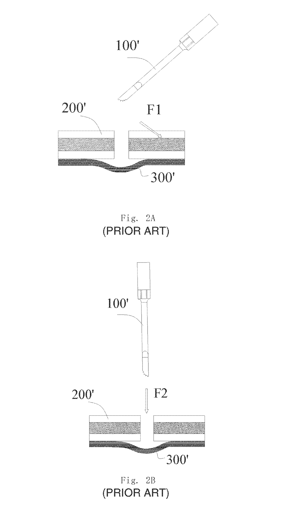
When the cutting operation is desired, the tool bit 100′ needs to apply the force downwardly to the osseous tissue, which may not only cause a low cutting speed and a low efficiency, but also cause the tool bit with a plurality of teeth to break in operation, as indicated by F2 in FIG. 2B.
However, in the process of a surgery, the tool bit 100′ of ultrasonic osteotome may be inserted into tissue 300′ such as marrow etc. accidentally, which brings unretrievable injury for a patient.
Moreover, the tool bit 100′ of ultrasonic osteotome has a complex shape and is difficult to be machined, thus, the production cost thereof is high.

Method used


Image

  • Tool bit of ultrasonic osteotome and ultrasonic osteotome including the same
  • Tool bit of ultrasonic osteotome and ultrasonic osteotome including the same
  • Tool bit of ultrasonic osteotome and ultrasonic osteotome including the same

Examples


Embodiment Construction

[0035]Next, the specific embodiments of the present invention will be described in detail with reference to accompanied figures. Throughout the description, identical or similar reference numerals represent identical or similar members. It should be noted that embodiments described herein are depicted only for illustration, instead of limiting to the present invention.

[0036]In the description of the present disclosure, it should be noted that the orientations or positions represented by the terms of “up”, “down”, “vertical”, “horizontal”, “top”, “bottom”, “inner” and “outer” and the like are based on the figures. It is given only by way of examples, instead of being intended to limit the device or element to have a special orientation or to be configured and operate in a special orientation. Thus, it cannot be understood as limiting of the present invention. In addition, the terms of “first” and “second” are depicted only by illustration, instead of being intended to define which on...


PUM


Abstract

Disclosed are a tool bit of an ultrasonic osteotome and an ultrasonic osteotome including the same, the tool bit comprising: an arbour (2); and an end portion (1) of the tool bit connected to a front end of arbour (2), wherein the end portion (1) of the tool bit has a hook-like shape and includes a hook tip (11), a hook handle (13), as well as a hook-shaped interconnecting piece (12) which is interconnected between the hook tip (11) and the hook handle (13). The hook handle (13) is connected with the arbour (2), and the inner side edge of the hook-shaped interconnecting piece (12) is tooth-like. With this ultrasonic osteotome, the cutting efficiency is high and surgery time is short, therefore the labour intensity of medical workers is decreased. Moreover, accurate positioning can be realized in cutting process with no skidding, so the chance of success of surgery can be improved.

Description

CROSS REFERENCE TO RELATED APPLICATIONS[0001]This is a Continuation application of International Application Serial No. PCT / CN2014 / 079580 filed on Jun. 10, 2014, which claims the benefit of Chinese Application No. 201320435092.7 filed on Jul. 22, 2013, the disclosures of which are hereby incorporated by reference.BACKGROUND[0002]1. Field of the Invention[0003]The present disclosure relates to a technical field of medical equipment, in particular to an improved tool bit of ultrasonic osteotome and an ultrasonic osteotome comprising the tool bit.[0004]2. Description of the Related Art[0005]In osteopathic surgery, an ultrasonic osteotome is usually used to perform cutting, grinding, planning, scraping, even arbitrary shaping on bones. FIG. 1A shows a typical structure of a conventional tool bit 100′ of ultrasonic osteotome, which has a plurality of teeth and a wide tip, and a majority part of the tip does not constitute an effective main cutting part, as shown in FIG. 1B.[0006]The tool...

Claims


Application Information

Patent Timeline
Patent Type & Authority Patents(United States)
IPC IPC(8): A61B17/32A61B17/14A61B17/16A61B17/3209A61B17/3205
CPCA61B17/320068A61B17/3209A61B17/142A61B17/144A61B17/1604A61B17/32A61B17/1659A61B17/3205A61B2017/320072A61B2017/320075
Inventor CAOLI, CHUNYUAN
Owner CAO
Learn More