
Manipulator and machine tool

A manipulator and track technology, applied in the directions of manipulators, metal processing, chucks, etc., can solve the problems of center position deviation and low grasping accuracy of the workpiece to be processed, and achieve the effect of precise clamping and alleviating the low grasping accuracy.

Pending Publication Date: 2017-06-13
NINGBO ZEE AUTOMATION EQUIP
View PDF6 Cites 8 Cited by
  • Summary
  • Abstract
  • Description
  • Claims
  • Application Information

AI Technical Summary

Problems solved by technology

[0005] In view of this, the object of the present invention is to provide a manipulator and a machine tool to alleviate the technical problem of low grasping accuracy caused by the manipulator device in the prior art, which tends to shift the center position of the workpiece to be grasped.

Method used


Image

  • Manipulator and machine tool
  • Manipulator and machine tool
  • Manipulator and machine tool

Examples


Embodiment 1

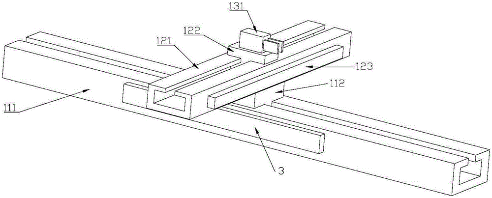
[0033] A kind of manipulator provided by the embodiment of the present invention, such as figure 2As shown, it includes: a longitudinal moving assembly, a lateral moving assembly and a clamping assembly 131, wherein,

[0034] The longitudinal movement assembly includes a first rail 111, a first slider 112 and a first driving part 3, and the first driving part 3 is used to drive the first slider 112 to move longitudinally along the first rail 111 in the horizontal direction;

[0035] The lateral movement assembly includes a second rail 121, a second slider 122 and a second driving part 123, and the second driving part 123 is used to drive the second slider 122 to move laterally along the second rail 121 in the horizontal direction;

[0036] The first slider 112 is fixedly connected to the second track 121 , and the second slider 122 is fixedly connected to the clamping assembly 131 , and the lateral movement and the longitudinal movement are movements in directions perpendicul...

Embodiment 2

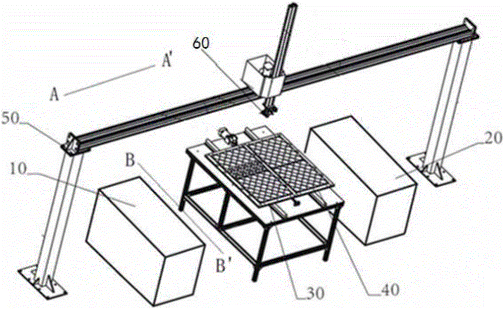
[0062] A machine tool provided by an embodiment of the present invention includes: a workpiece processing component, a controller and Figure 2 to Figure 4 For any manipulator provided in the first shown embodiment, the controller is respectively connected with the first drive part 3, the second drive part 123, the third drive part 53 and the fourth drive part 54 of the manipulator, and the workpiece processing part is The workpiece to be processed held by the manipulator is processed.

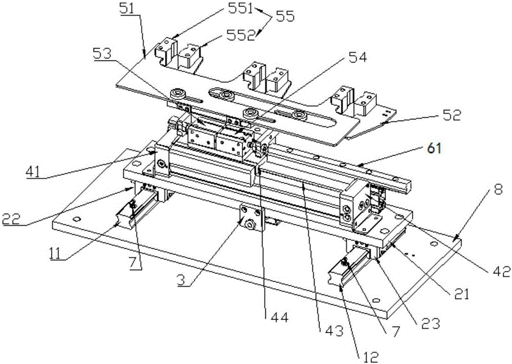
[0063] Specifically, the controller controls the first driving part 3 to drive the sliding of the first slider 112, controls the second driving part 123 to drive the second sliding block 122 to slide, controls the third driving part 53 to drive the upper manipulator 51 to move, and controls the fourth driving part 53 to drive the upper manipulator 51 to move. The component 54 drives the lower manipulator 52 to move.

[0064]In the embodiment of the present invention, the first slider 112 is f...


PUM


Abstract

The invention provides a manipulator and a machine tool and relates to the technical field of auxiliary machining equipment. The manipulator comprises a longitudinal moving assembly, a horizontal moving assembly and a clamping assembly, wherein the longitudinal moving assembly comprises a first track, a first slider and a first driving part which is used for driving the first slider to move longitudinally along the first track in the horizontal direction; the horizontal moving assembly comprises a second track, a second slider and a second driving part which is used for driving the second slider to move horizontally along the second track in the horizontal direction; the first slider is fixedly connected with the second track, the second slider is fixedly connected with the clamping assembly, and horizontal movement and longitudinal movement are performed in mutually perpendicular directions. The technical problem of lower grabbing precision caused by the fact that a manipulator device enables central position of a grabbed to-be-machined workpiece to deviate easily in the prior art is solved.

Description

technical field [0001] The invention relates to the technical field of mechanical processing auxiliary equipment, in particular to a manipulator and a machine tool. Background technique [0002] Automation equipment refers to a collection of a series of equipment that cooperates with each other to automatically complete the workflow according to the set instructions or procedures without human intervention, including detection equipment, control equipment and execution equipment. The station manipulator belongs to the execution equipment part of the automation equipment, and has a wide range of applications in industry, agriculture, military, scientific research, transportation, commerce, medical treatment, service and family. The use of manipulators can not only liberate people from heavy physical labor, some mental work, and harsh and dangerous working environments, but also expand human organ functions, greatly improve labor productivity, and enhance human understanding o...

Claims


Application Information

Patent Timeline
Patent Type & Authority Applications(China)
IPC IPC(8): B25J15/00B23Q7/04
CPCB23Q7/043B23Q7/048B25J15/0052
Inventor 刘建军马盈丰
Owner NINGBO ZEE AUTOMATION EQUIP
Learn More