Eureka AIR delivers breakthrough ideas for toughest innovation challenges, trusted by R&D personnel around the world.

Positioning device and lens module assembling apparatus

A technology for positioning devices and lens modules, applied in installation, instrumentation, optics, etc., can solve problems such as lower assembly yield, difficult cleaning, and damage to lens module components

Inactive Publication Date: 2007-12-12
HONG FU JIN PRECISION IND (SHENZHEN) CO LTD +1
View PDF0 Cites 5 Cited by
  • Summary
  • Abstract
  • Description
  • Claims
  • Application Information

AI Technical Summary

Problems solved by technology

[0004] However, the trays of each lens module component station may be skewed, and each lens module component may be placed on its tray skewed, while the retrieving device is still in accordance with its pre-set and lens module in the tray. If the components extend down in the vertical direction, each lens module component may be sucked or clamped eccentrically. In this way, when the take-up device moves above the center of the lens barrel and holds it, the take-up device cannot smoothly remove the lens module components. Putting it into the lens barrel may directly damage or drop the precise lens module components, and it is not easy to clean up after falling. After cleaning, many of them may become waste products, resulting in lower assembly yield.
On the other hand, if the lens barrel is skewed in the carrying jig, it will also reduce the assembly yield

Method used


Image

  • Positioning device and lens module assembling apparatus
  • Positioning device and lens module assembling apparatus
  • Positioning device and lens module assembling apparatus

Examples


Embodiment Construction

[0016] The positioning device and lens module assembly equipment provided by the present invention will be further described in detail below in conjunction with the accompanying drawings.

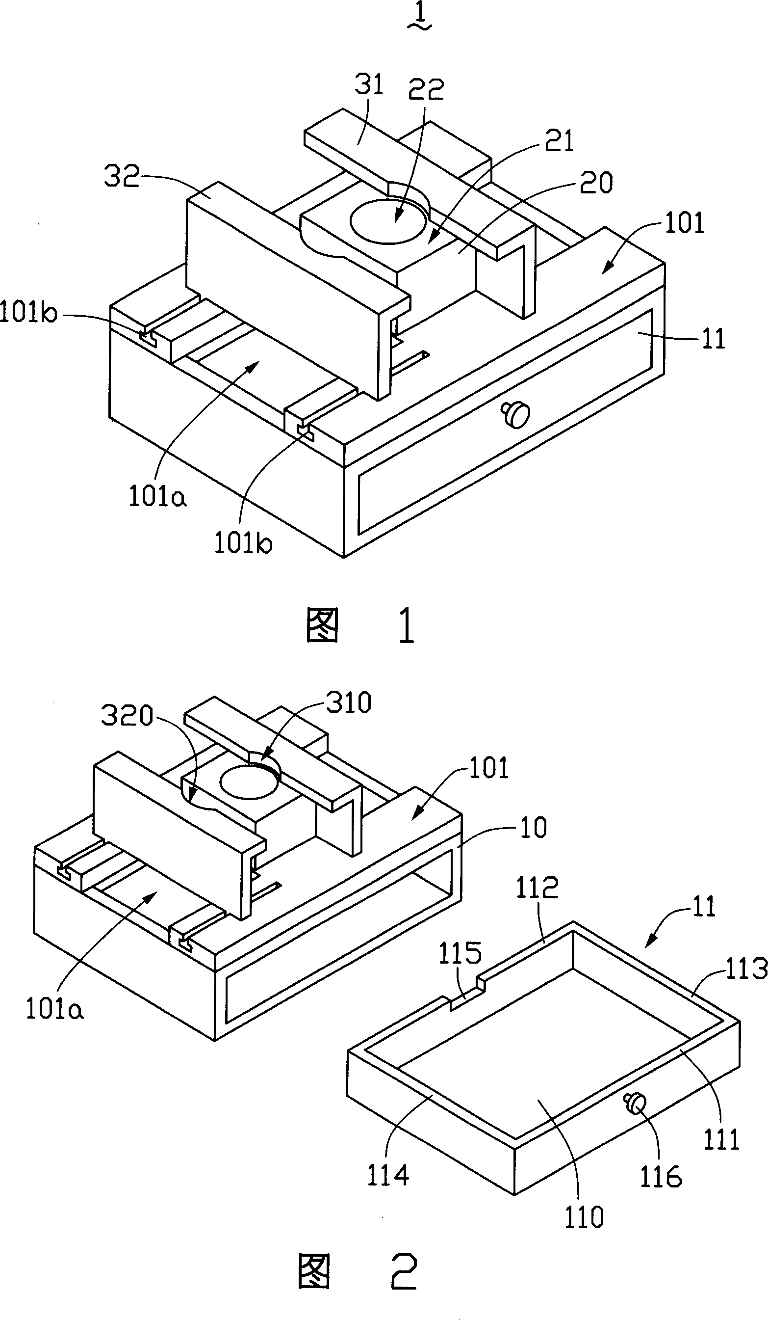
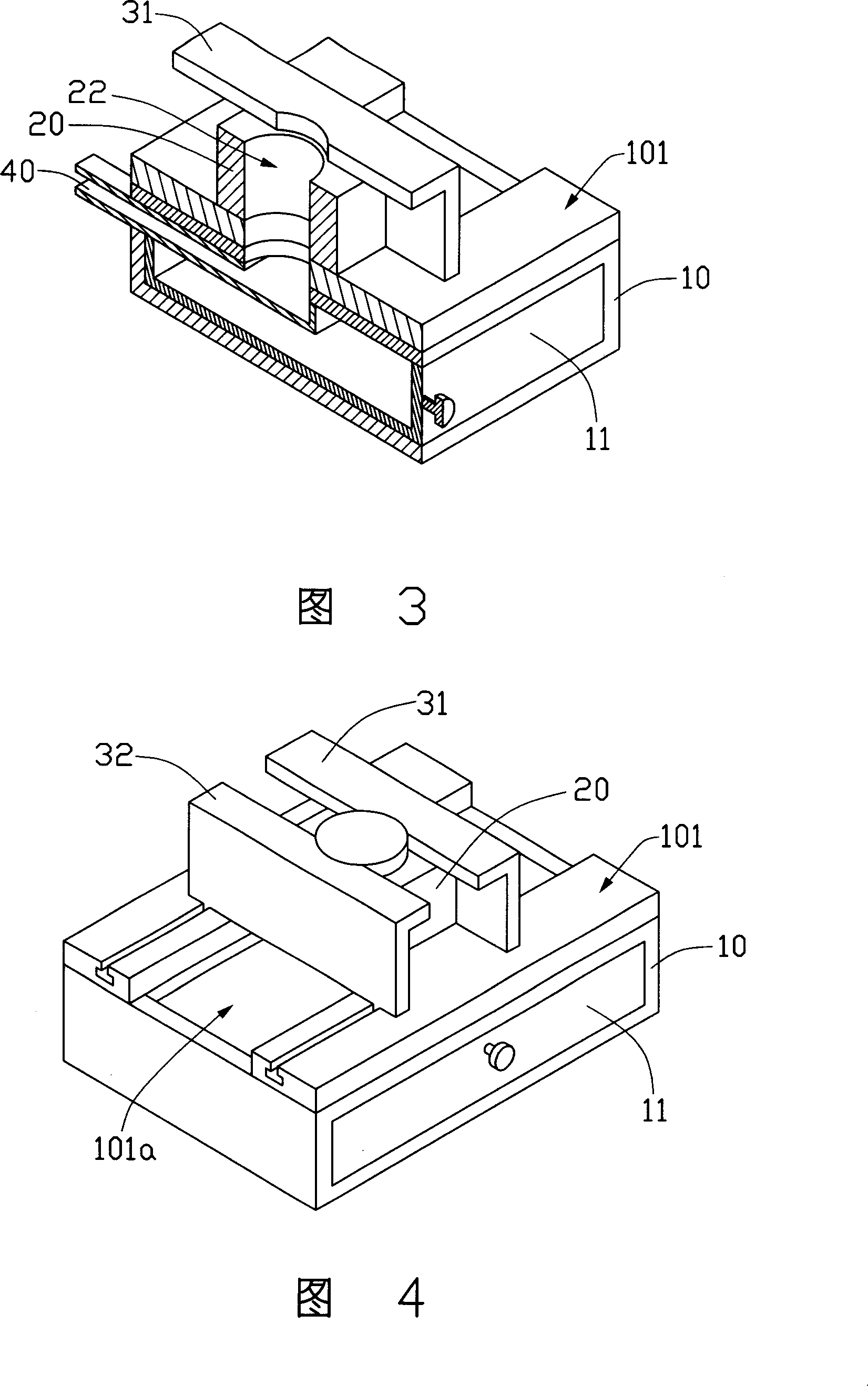
[0017] Please refer to FIGS. 1 to 3 together. The positioning device 1 provided by the embodiment of the present invention includes a base 10, a bearing body 20 disposed on the base 10, a first positioning block 31, and a The second positioning block 32 .

[0018] A storage drawer 11 is disposed under the surface 101 of the base 10 , and the surface 101 is provided with an opening 101 a communicating with the storage drawer 11 . The storage drawer 11 is a hollow square, including a square bottom 110, and two front and rear side walls 111, 112 and two left and right side walls 113, 114 vertically extending from the edge of the square bottom 110. The storage drawer 11 A groove 115 is opened on the rear side wall 112 , and a handle 116 is protruded from the outer surface of the front side wal...


PUM


Abstract

A positioning device for lens module component and lens cone comprises a base, a bearing body on the surface of the base for the lens module component or lens cone, and the first and the second positioning block for the lens module or the lens cone, a storage drawer inside the base with its surface with notch connected to the storage drawer. It also provides a lens module assembly device for the said positioning device.

Description

technical field [0001] The invention relates to the technical field of lens module assembly, in particular to a positioning device and lens module assembly equipment using the positioning device. Background technique [0002] With the development of camera technology, lens modules are widely used in camera devices for various purposes. The combination of lens modules and various portable electronic devices such as mobile phones, cameras, computers, etc. is favored by many consumers. . [0003] When the lens module assembles its lens module components, one or more lens barrels on the material tray of the lens barrel station are usually clamped by a clip and other picking device and placed into a carrying fixture, which carries the lens barrel The carrying fixture is conveyed to each lens module component station by a conveyor belt, and is extended to the lens module component station material tray with a suction nozzle, clip or manipulator, etc., to suck or clamp the lens mo...

Claims


Application Information

Patent Timeline
Patent Type & Authority Applications(China)
IPC IPC(8): G02B7/02
Inventor 吴承勋
Owner HONG FU JIN PRECISION IND (SHENZHEN) CO LTD
Why Eureka
Eureka Blog
Learn More