Waste collection device applied to door panel numerical control combined punching

A waste collection and door panel technology, applied in stripping devices, manufacturing tools, pushing equipment, etc., can solve the problems of low waste collection efficiency and high collection labor costs

Active Publication Date: 2019-03-12
DEYANG KAIDA DOORS
View PDF5 Cites 0 Cited by
  • Summary
  • Abstract
  • Description
  • Claims
  • Application Information

AI Technical Summary

Problems solved by technology

[0003] The purpose of the present invention is to provide a waste material collection device applied to door panel numerical control combination punching, to solve the problems of high labor cost and low waste collection efficiency of traditional punching waste material collection

Method used


Image

  • Waste collection device applied to door panel numerical control combined punching
  • Waste collection device applied to door panel numerical control combined punching
  • Waste collection device applied to door panel numerical control combined punching

Examples


Embodiment 1

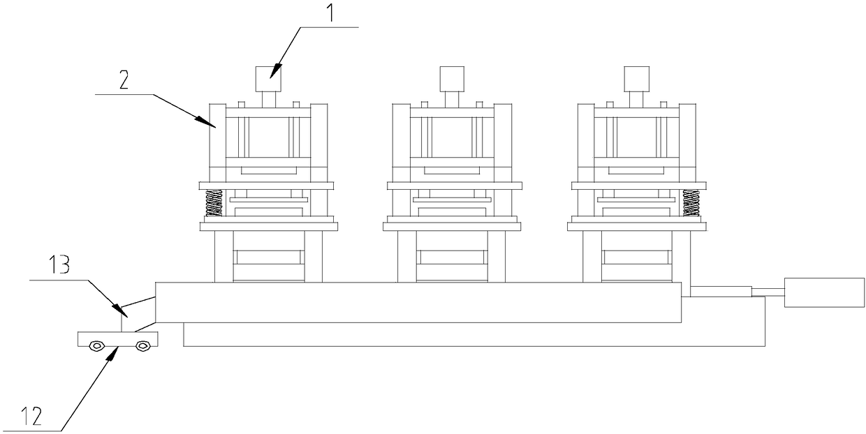
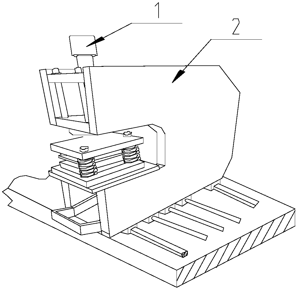
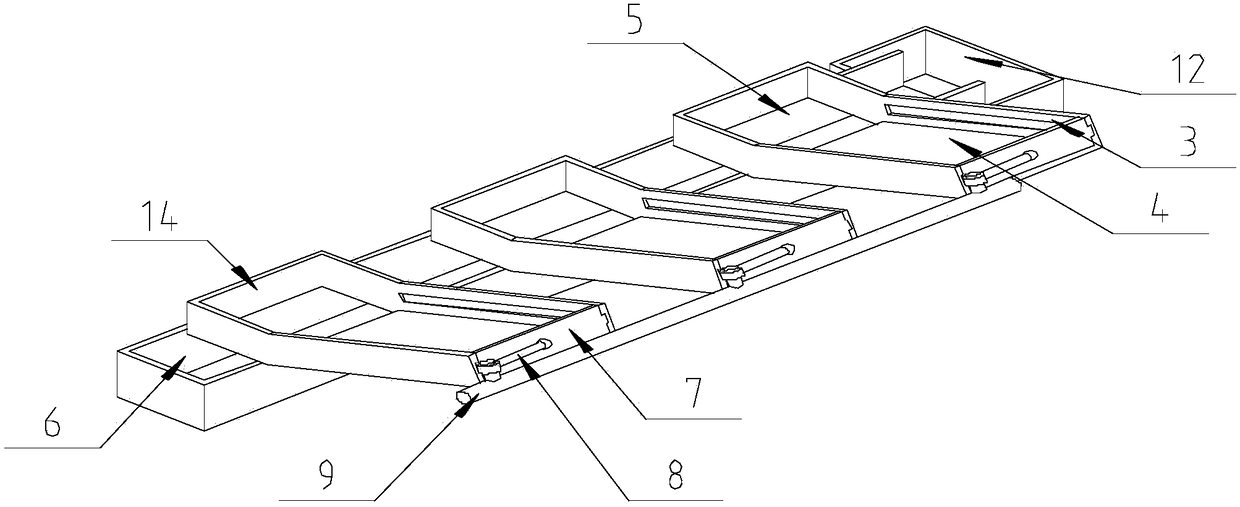
[0026] Such as Figure 1-Figure 6 As shown, the present invention is applied to a waste collection device for door panel numerical control combination punching, including several punching dies 1 and several pairs of support plates 2, and the punching dies 1 are arranged in the middle of a pair of support plates 2, and on the support plates 2 One end close to the ground cooperates with the screw, and connecting plates 3 are arranged on the opposite surfaces of a pair of supporting plates 2. The connecting plates 3 are parallel to the supporting plates 2, and a material holding plate 4 is vertically arranged between the connecting plates 3. , the material holding plate 4 is used to hold the waste produced when the punching die 1 is punched, the connecting plate 3 and the material holding plate 4 are all located below the waste material of the punching die 1, and the connecting plate 3 and the material holding plate On the board 4, one end close to the upper door panel protrudes ...

Embodiment 2

[0033] This embodiment is based on Embodiment 1 to further illustrate the present invention.

[0034]The push rod 9 is still supported by a traditional bearing seat. At the same time, a positioning plate and a spring are arranged on the end of the push rod 9 away from the driving device. The positioning plate is vertically fixed on the ground, and one end of the spring is connected with the end face of the push rod 9. The other end of spring 9 is connected with the side wall of positioning plate. When push pedal 7 was positioned at an end away from the upper door panel, the spring was in a normal state, and when push pedal 7 pushed waste materials into the leakage hole 5, the spring was in a compressed state. When the push plate 7 needs to be returned, the spring in the compressed state generates a thrust to the push rod 9, and the push rod 9 is returned by the thrust, which can reduce the energy consumption of the driving device when returning.

Embodiment 3

[0036] This embodiment is based on Embodiment 1 to further illustrate the present invention.

[0037] One end of the connecting plate 3 close to the upper door panel is provided with a baffle plate 14, the baffle plate 14 is perpendicular to the ground, the material baffle plate 14 can block the waste material pushed over from the material holding plate 4, so that the waste material can only be discharged from the leaking material. Leaked out of hole 5.


PUM


Abstract

The invention discloses a scrap collecting device applied to numerical-control combined punch for door panels. The scrap collecting device comprises punching dies and supporting plates of the punching dies. Opposite sides of each pair of supporting plates are provided with connecting plates which are parallel to the supporting plates; a containing plate is vertically arranged between the connecting plates and used for containing scraps generated during punching of the punching dies; the connecting plates and the containing plate are both arranged under the position, where scraps discharged, of the corresponding punching die; one end of each of the connecting plates as well as one end of the containing plate, close to an upper door panel material, both extend out of the opposite sides of each pair of supporting plates; the end, close to the upper door panel, of the containing plate is provided with a drain hole; a scrap groove is formed under the drain hole. The scraps fall into the containing plates and then roll into the scrap grooves, thus the scraps generated during punching of the all the punching dies of the numerical-control combined punch can be collected conveniently, and the problems of high labor cost and low scrap collection efficiency of the conventional punch scrap collection ways are solved.

Description

technical field [0001] The invention relates to a waste material collection device, in particular to a waste material collection device applied to a door panel numerically controlled combination punch. Background technique [0002] The punching die is a die that punches a material through a combination of concave and convex dies. In actual production, a part needs to be punched multiple times to obtain multiple through holes, so multiple punching dies are assembled together. Different types of products need to be punched at different positions. If the punching die is moved manually or multiple punching dies are combined according to the product model, it is not only time-consuming and laborious, but also increases the equipment wear cost of the workshop. The hole die is supported by a support plate, and a screw rod and the support plate are used. One punching die corresponds to one screw rod, and then the motor that drives the screw rod is controlled by the controller. Whe...

Claims


Application Information

Patent Timeline
Patent Type & Authority Patents(China)
IPC IPC(8): B21D28/26B21D28/34B21D45/00
CPCB21D28/26B21D28/34B21D45/003B21D45/02
Inventor 邓洪
Owner DEYANG KAIDA DOORS
Why Eureka
Try Eureka