
Novel stirrer for building

A construction and mixer technology, which is applied to cement mixing devices, cleaning methods and utensils, cleaning hollow objects, etc., can solve the problems of large mixing dead angle, affecting the mixing effect, insufficient and uniform mixing, etc., to reduce the mixing dead angle, The effect of reducing labor intensity

Inactive Publication Date: 2017-06-06
CHENGDU JIAMEIJIA SCI & TECH
View PDF5 Cites 15 Cited by
  • Summary
  • Abstract
  • Description
  • Claims
  • Application Information

AI Technical Summary

Problems solved by technology

But at the same time, the existing problem is that, for the existing mixers, due to the limitations of structure and design, the mixing is often not sufficient and uniform, especially there is a large gap at the inner bottom of the mixing cylinder. Stirring dead angle, which greatly affects the effect of stirring
At the same time, when the mixing work is completed, a large amount of building materials tend to stick to the inner wall of the mixing cylinder, and these sticky building materials are often difficult to wash off directly with water, which brings great difficulties to the cleaning work of the mixer. Inconvenience, and these have also greatly affected the performance of the existing mixer

Method used


Image

  • Novel stirrer for building

Examples


Embodiment Construction

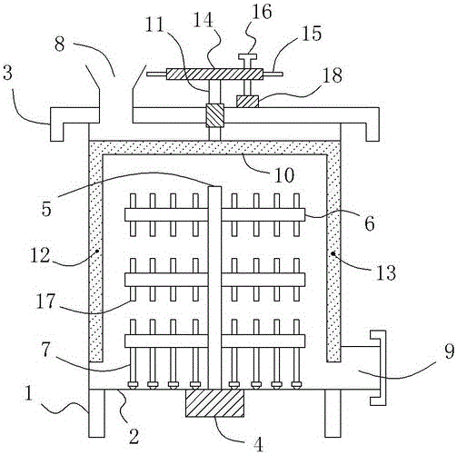
[0014] Such as figure 1 As shown, a new construction mixer includes a bracket 1 and a cylinder 2 arranged on the bracket 1, a cylinder cover 3 is provided on the top of the cylinder 2, and a bottom motor is also provided at the outer bottom of the cylinder 2. 4. The output shaft of the bottom motor 4 is set vertically upwards and extends to the inside of the barrel 2, and the top of the output shaft of the bottom motor 4 is also connected to a vertically upwardly extending shaft 5, which is also from top to bottom on the shaft 5 There are a plurality of horizontally arranged stirring rods 6; on the stirring rod 6 at the bottom of the rotating shaft 5, a plurality of bottom struts 7 extending vertically downwards are fixedly connected, so that between the stirring rods 6 and the bottom struts 7 Under the action of stirring, the building materials can be fully and evenly stirred, and the dead angle of stirring at the inner bottom of the cylinder 2 is greatly reduced. There is al...


PUM


Abstract

The invention relates to a novel stirrer for a building. The novel stirrer comprises a support, a barrel body and a barrel cover, wherein a bottom motor is arranged at the bottom end outside the barrel body; a rotary shaft is connected to the top end of the output shaft of the bottom motor; a plurality of stirring rods are arranged on the rotary shaft; a plurality of bottom support rods are connected to the stirring rod located at the bottommost part of the rotary shaft; a charge port is formed in the barrel cover; a discharge port is formed in the bottom of the right side of the barrel body; a cross rod is arranged at the top end in the barrel body; a top vertical rod is connected to the middle of the cross rod; the top vertical rod penetrates upwards through the barrel cover and is rotationally connected with the barrel cover through a bearing; a left scraping rod and a right scraping rod are connected to the left end and the right end of the cross rod separately; the left scraping rod and the right scraping rod are both closely bonded with the vertical inner sidewall of the barrel body; a circular disc is arranged at the top end of the top vertical rod; a handle is arranged at the outer circumference of the circular disc; a thread hole is formed in the circular disc; and a screw rod is further in threaded connection into the thread hole. Through the abovementioned structure, the novel stirrer disclosed by the invention is capable of greatly reducing stirring dead angles during a stirring process, and further greatly lowering the labour intensity during cleaning.

Description

technical field [0001] The invention relates to a new construction mixer. Background technique [0002] In the field of building construction, it is often necessary to mix building materials such as building mortar or cement, so a corresponding mixer is required. But at the same time, the existing problem is that, for existing mixers, due to limitations in structure and design, the mixing is often insufficient and uniform, especially at the inner bottom of the mixing cylinder. Stirring dead angle, which greatly affects the effect of stirring. At the same time, when the mixing work is completed, a large amount of building materials tend to stick to the inner wall of the mixing cylinder, and these sticky building materials are often difficult to wash off directly with water, which brings great difficulties to the cleaning work of the mixer. Inconvenience, and these have also all greatly influenced the performance of existing mixer. Contents of the invention [0003] In or...

Claims


Application Information

Patent Timeline
Patent Type & Authority Applications(China)
IPC IPC(8): B28C5/16B28C5/08B08B9/087
CPCB28C5/16B08B9/0808B28C5/0806
Inventor 秦熙珍
Owner CHENGDU JIAMEIJIA SCI & TECH
Learn More