Refrigeration cycle device
A technology of circulation device and expansion device, which is applied in the field of refrigeration cycle devices, can solve the problems such as the decline of refrigeration capacity of refrigeration cycle devices, and achieve the effects of preventing condensation, increasing condensation temperature, and preventing condensation
- Summary
- Abstract
- Description
- Claims
- Application Information
AI Technical Summary
Problems solved by technology
Method used
Image

Examples
Embodiment approach 1
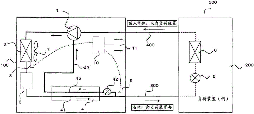
[0023] figure 1 This is an example of the refrigerant circuit configuration of the refrigeration cycle apparatus 500 according to Embodiment 1 of the present invention.
[0024] Description of the structure of the refrigeration cycle device 500
[0025] figure 1 The refrigerating cycle device 500 has: a load device 200, which is equivalent to a refrigerator, for example, and is installed indoors, and cools the space in which food and other storage items are placed in the refrigerator; a heat source device 100, which is, for example, Installed outdoors or the like; the piping 300 and the piping 400 connecting the load device 200 and the heat source device 100 . The pipe 300 is a pipe through which liquid refrigerant passes, and the pipe 400 is a pipe through which suction gas passes.
[0026] The refrigeration cycle apparatus 500 has: a compressor 1 that compresses the refrigerant and discharges it; a condenser 2 (radiator) that condenses the refrigerant; a liquid storage un...
Embodiment approach 2
[0067] In Embodiment 1, the method of stopping or decelerating the condenser fan 7 when the temperature difference obtained by subtracting the value of the pipe temperature of the pipe 300 from the value of the suction temperature of the condenser 2 exceeds the set value was described. However, in this embodiment, a configuration in which the set value can be further changed from the heat source device 100 and the air volume of the condenser fan 7 can be changed according to the set value will be described.
[0068] The refrigeration cycle apparatus 500 of the present embodiment includes a display unit for setting values and the like, and a setting unit 11 as an input unit for the set values in the control unit 10 in the heat source unit 100 .
[0069] The refrigerant circuit diagram and operation of the refrigeration cycle apparatus 500 of this embodiment are the same as those of the first embodiment.
[0070] The control device 10 periodically reads the detection value o...
Embodiment approach 3
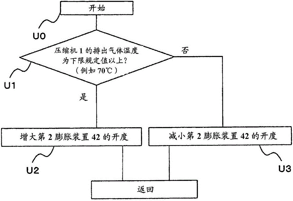
[0075] In this embodiment, the refrigeration cycle apparatus 500 of Embodiment 1 and Embodiment 2 will be described in which not only the air volume of the condenser fan 7 is adjusted, but also the configuration in which dew condensation is suppressed by adjusting the opening degree of the second expansion device 42 will be described. .
[0076] By adjusting the opening degree of the second expansion device 42, the flow of the refrigerant cycle during dew condensation is suppressed
[0077] The refrigeration cycle apparatus 500 of this embodiment is the same refrigerant circuit as that of the first and second embodiments.
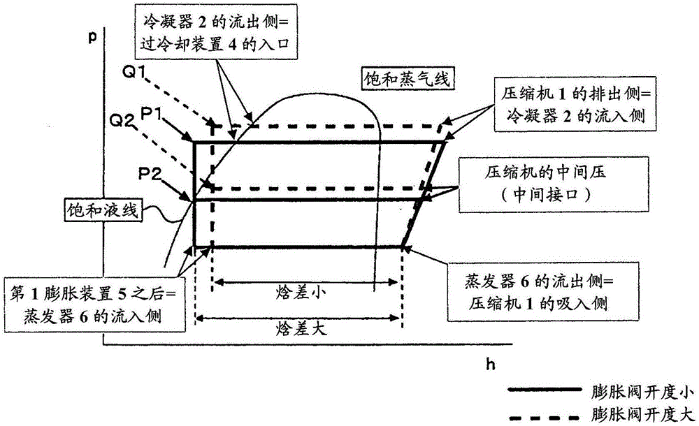
[0078] By instructing the control device 10 from the setting device 11, the refrigeration cycle device 500 can be operated by switching to a mode in which the refrigerant passing through the subcooling device 4 has a large degree of subcooling, that is, the refrigerating capacity is prioritized. mode, and the mode that does not increase the supercooling de...
PUM
 Abstract
Description
Claims
Application Information
 - R&D
- Intellectual Property
- Life Sciences
- Materials
- Tech Scout
- Unparalleled Data Quality
- Higher Quality Content
- 60% Fewer Hallucinations
Browse by: Latest US Patents, China's latest patents, Technical Efficacy Thesaurus, Application Domain, Technology Topic, Popular Technical Reports.
© 2025 PatSnap. All rights reserved.Legal|Privacy policy|Modern Slavery Act Transparency Statement|Sitemap|About US| Contact US: help@patsnap.com