
Electronic component inserter and insertion method

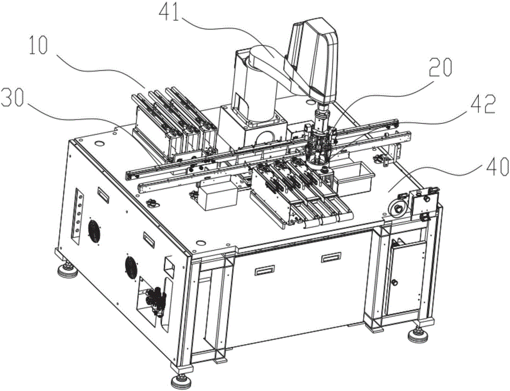
A technology for electronic components and plug-in machines, which is applied to electrical components, electrical components, etc., can solve the problems of low production efficiency and high labor intensity, and achieve the effects of simple structure, high degree of automation, and small space occupation.

Pending Publication Date: 2017-05-31
长沙市赛稳柒智能设备有限公司
View PDF5 Cites 7 Cited by
  • Summary
  • Abstract
  • Description
  • Claims
  • Application Information

AI Technical Summary

Problems solved by technology

[0002] With the rapid development of electronic technology, the use of electronic products is becoming more and more extensive. PCB circuit boards are important equipment for electronic products. The electronic components on the PCB circuit board are soldered to the substrate through plug-ins. Workers on the assembly line carry out, labor-intensive and low production efficiency

Method used


Image

  • Electronic component inserter and insertion method
  • Electronic component inserter and insertion method
  • Electronic component inserter and insertion method

Examples


Embodiment Construction

[0036] In order to facilitate the understanding of the present invention, the present invention will be described more fully below with reference to the associated drawings. Preferred embodiments of the invention are shown in the accompanying drawings. However, the present invention can be embodied in many different forms and is not limited to the embodiments described herein. On the contrary, these embodiments are provided to make the understanding of the disclosure of the present invention more thorough and comprehensive.

[0037] Unless otherwise defined, all technical and scientific terms used herein have the same meaning as commonly understood by one of ordinary skill in the technical field of the invention. The terms used herein in the description of the present invention are for the purpose of describing specific embodiments only, and are not intended to limit the present invention.

[0038] It should be noted that when an element is said to be "connected" to another ...


PUM


Abstract

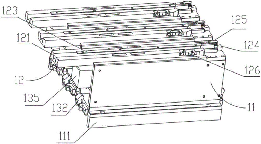
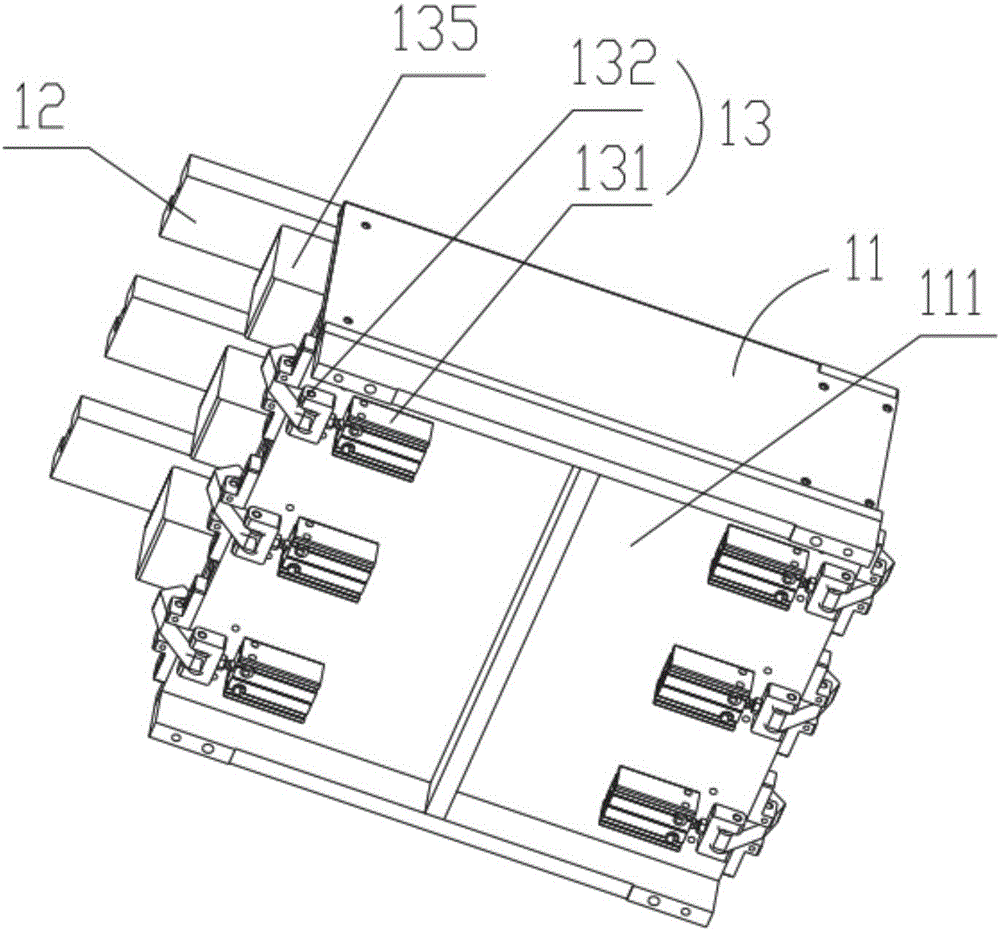
The invention discloses an electronic component inserter. The electronic component inserter comprises a rack, an electronic component feeding device, an electronic component grabbing device, a material conveying device, a position capturing device, a sensing mechanism and a control device. The electronic component inserter disclosed by the invention has the advantages of being high in production efficiency and high in automatic degree. The invention further discloses an insertion method using the electronic component inserter.

Description

technical field [0001] The invention relates to the field of plug-in machines, in particular to an electronic component plug-in machine and a plug-in method. Background technique [0002] With the rapid development of electronic technology, the use of electronic products is becoming more and more extensive. PCB circuit boards are important equipment for electronic products. The electronic components on the PCB circuit board are soldered to the substrate through plug-ins. Workers on the assembly line carry out the process, which is labor-intensive and low in production efficiency. Contents of the invention [0003] The purpose of the present invention is to overcome the deficiencies of the prior art, to provide an electronic component insertion machine with high production efficiency and high degree of automation, and its insertion method [0004] The present invention can be realized by taking the following technical solutions: [0005] An electronic component insertion ...

Claims


Application Information

Patent Timeline
IPC IPC(8): H05K13/04
CPCH05K13/0404H05K13/0417
Inventor 高荣
Owner 长沙市赛稳柒智能设备有限公司
Learn More