
A sensor circuit for both contact and non-contact detection

A sensor circuit, non-contact technology, applied in the direction of measuring electrical variables, measuring current/voltage, instruments, etc., to achieve the effect of simple circuit structure, increasing filter characteristics, and reducing noise

Active Publication Date: 2020-07-17
南京和协集成电路科技有限公司
View PDF2 Cites 0 Cited by
  • Summary
  • Abstract
  • Description
  • Claims
  • Application Information

AI Technical Summary

Problems solved by technology

[0004] At present, the contact detection circuit and the non-contact detection circuit are realized by different circuits, and there is no one circuit that can be used for both contact detection and non-contact detection.

Method used


Image

  • A sensor circuit for both contact and non-contact detection
  • A sensor circuit for both contact and non-contact detection
  • A sensor circuit for both contact and non-contact detection

Examples


Embodiment 1

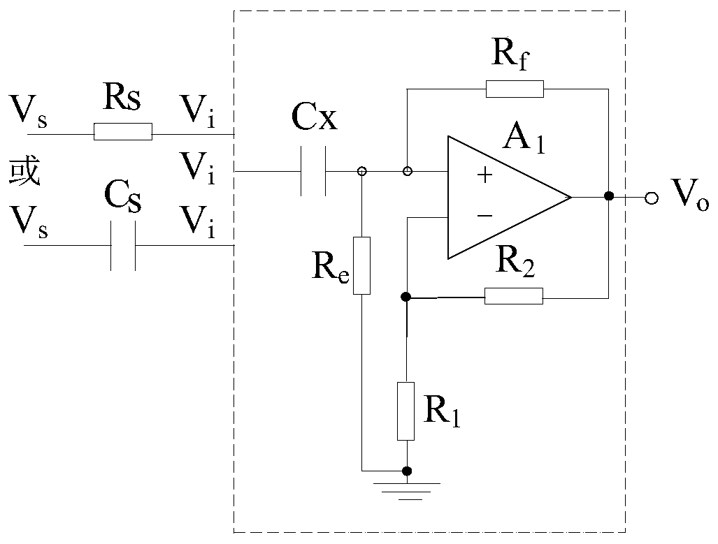
[0023] see figure 1 , including only the detection part and the basic part of the circuit. When this method realizes the contact detection, the electrode commonly used in the prior art can be used as the detection component to contact the measured signal Vs, and the measurement signal is generated and transmitted to the circuit input terminal Vi. The equivalent circuit is as follows figure 1 Shown for Rs. When realizing non-contact detection, it is realized by capacitive coupling. The capacitive coupling device commonly used in the prior art can be used as the detection component to detect the measured signal Vs, and the measurement signal is generated and transmitted to the circuit input terminal Vi. The equivalent circuit is as follows: figure 1 Cs shown, Cx should be greater than the maximum Cs in this application. The basic part of the circuit includes capacitor Cx, resistor Re, resistor Rf, resistor R 1 , resistance R 2 And the operational amplifier, one end of the ca...

Embodiment 2

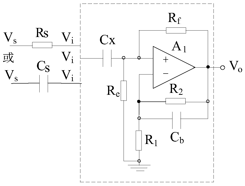
[0027] see figure 2 , including the detection part, the basic part of the circuit and a part of the circuit filtering part. The sensing and detection components remain unchanged, and the sensing circuit part is figure 1 circuit based on the resistor R at the output and the inverting input of the operational amplifier 2 The capacitor Cb is connected in parallel to realize low-pass filtering, limit the bandwidth of the detection signal, and reduce the noise floor of the circuit at the same time.

Embodiment 3

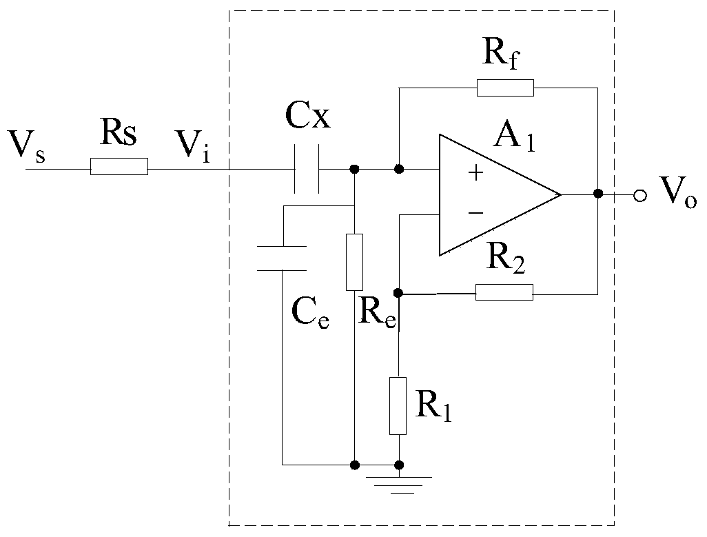
[0029] see image 3 , including the detection part, the basic part of the circuit and a part of the circuit filtering part. The sensing and detection components remain unchanged, and the sensing circuit part is figure 1 On the basis of the circuit, a capacitor Ce is connected in parallel to the resistor Re from the non-inverting input of the operational amplifier to the ground to realize low-pass filtering, limit the bandwidth of the detection signal, and reduce the noise floor of the circuit at the same time. In non-contact detection applications, if this method is adopted, in order to ensure the detection sensitivity, the value of the capacitance Cx should be greater than the maximum value of the capacitance Cs, and the value of the capacitance Ce should be smaller than the minimum value of the capacitance Cs.


PUM


Abstract

A novel sensor circuit applicable to both contact detection and non-contact detection, comprising: a capacitor Cx, a resistor Re, a resistor Rf, a resistor R1, a resistor R2, and an operational amplifier A1. One end of the capacitor Cx is connected to a detection signal and the other end thereof is connected to a non-inverting input end of the operational amplifier A1; one end of the resistor Re is connected to the non-inverting input end of the operational amplifier A1 and the other end thereof is grounded; one end of the resistor Rf is connected to the non-inverting input end of the operational amplifier A1 and the other end thereof is connected to an output end of the operational amplifier A1; one end of the resistor R1 is connected to an inverting input end of the operational amplifier A1 and the other end thereof is grounded; one end of the resistor R2 is connected to the inverting input end of the operational amplifier A1 and the other end thereof is connected to the output end of the operational amplifier A1. The sensor has a simple circuit structure, is applicable to both contact detection and non-contact detection, can effectively avoid a change in circuit performance caused by a change in contact resistance or coupling capacitance, and can effectively reduce noise caused by the change in circuit performance.

Description

technical field [0001] The present invention relates to a sensor detection circuit for measuring low-frequency voltage or electric field signals in various applications, including medical applications, environmental monitoring, navigation, ultra-low frequency communication and other fields, such as measurement of bioelectrical signals, biochemical analysis, and ultra-low frequency signal sources Detection and positioning, long-distance cruise, etc. Background technique [0002] There are two types of low frequency (0.1Hz—10kHz) electrical signal detection methods: contact and non-contact. Both contact and non-contact detection need to overcome the impact of source impedance changes on circuit performance such as sensitivity, detection bandwidth, especially lower than the low-end cutoff frequency of 1Hz, etc., for which it is necessary to design a high input impedance detection circuit. [0003] In contact measurement, resistance of magnitude of megohm is usually directly us...

Claims


Application Information

Patent Timeline
Patent Type & Authority Patents(China)
IPC IPC(8): H03H11/28H03H11/46H03G3/30
CPCH03G3/3005H03H11/28H03H11/46G01R19/00
Inventor 张丽敏唐跃吴绒绒闫锋
Owner 南京和协集成电路科技有限公司
Learn More