
Method for testing initial position angle of motor rotor

A technology of initial position and motor rotor, applied in the direction of electronic commutator, electrical components, control system, etc., can solve the problems of the influence of the measurement accuracy of the motor load size, high test conditions, wrong values, etc., to achieve online fault diagnosis and The effect of error correction control, low test condition requirements and high accuracy

Active Publication Date: 2017-05-31
JING JIN ELECTRIC TECH HEZE CO LTD
View PDF3 Cites 11 Cited by
  • Summary
  • Abstract
  • Description
  • Claims
  • Application Information

AI Technical Summary

Problems solved by technology

This method requires high test conditions, the size of the motor load will have a great impact on the measurement accuracy, and the actual operation on site is not easy
[0009] Usually, in the motor control system, a parameter of the current position angle of the motor rotor is fed back, but this parameter may be a wrong value, or it may be a correct value, and it cannot be judged whether it is wrong or correct

Method used


Image

  • Method for testing initial position angle of motor rotor
  • Method for testing initial position angle of motor rotor

Examples


Embodiment 1

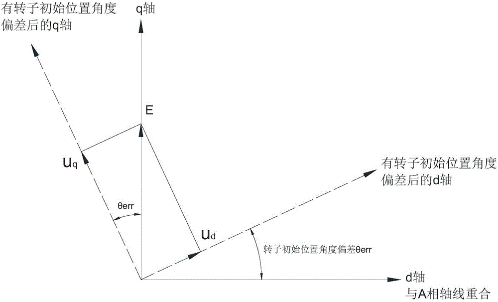
[0045] Such as figure 1 As shown, in Embodiment 1 of the present invention, a method for testing the initial position angle of the motor rotor includes the following steps:

[0046] Step 1, first give the motor to be tested a current i to make the motor run; the frequency of the current i is relatively low, and it can be tested as long as the motor rotates. The current frequency determines the speed at which the motor rotates, so the frequency of the current i can be within the rated speed range If the frequency of the current i is 1 / 3 of the rated frequency of the motor.

[0047] Step 2, after the motor is running, make the current i zero;

[0048] Step 3, measure the voltage u of the d-axis and q-axis of the motor stator at this time d , uq ;

[0049] Step 4, according to u d , u q The trigonometric function relationship between calculates the initial position angle deviation θ of the motor rotor at this time err .

[0050] The motor tested in this embodiment is a syn...

Embodiment 2

[0080] In Embodiment 2 of the present invention, the initial position angle deviation θ of the motor rotor err The trigonometric function relationship of is expressed as follows:

[0081] When the motor rotates forward, the θ err =arccot2(u q , u d ).

[0082] When the motor rotates in reverse, the θ err =arccot2(-u q ,-u d ).


PUM


Abstract

The invention discloses a method for testing initial position angle of a motor rotor and solves the technical problem that the prior art is high in requirements on initial position angle testing conditions of the motor rotor and difficult in actual operation. The method includes following steps: step 1, applying a current i on a to-be-tested motor to enable the same to run; step 2, after the motor runs, enabling the current i to be zero; step 3, measuring voltage ud and uq of a shaft d and a shaft q of a motor stator; step 4, calculating according to a triangular function relation between ud and uq to acquire initial position angle deviation theta err of the motor rotor. The initial position angle deviation of the motor rotor is calculated by directly using the voltage of the d shaft and the q shaft of the motor stator, and corresponding relation between voltage at the motor end in a motor controller and the initial rotor position angle is made clear; the method is simple and suitable for engineering site operation; online fault diagnosis and error correction control can be realized, and system function safety can be improved.

Description

technical field [0001] The invention relates to a method for testing the initial position angle of the motor rotor, which is used for detecting the initial position angle of the motor rotor. Background technique [0002] With the development and promotion of new energy vehicle technology, the servo performance requirements of motor drives are getting higher and higher. The motor control adopts the vector control method, and the initial position angle of the motor rotor is an important parameter in the vector control, which needs to be tested in advance. [0003] The initial position angle of the motor rotor is an important parameter in motor control. Its accuracy has an important impact on the performance of the motor. Many practical problems encountered in the field are related to the initial position angle error of the motor rotor. The initial position of the motor rotor Accuracy of angle measurement and measurement is critical. [0004] When performing vector control on...

Claims


Application Information

Patent Timeline
IPC IPC(8): H02P6/18
CPCH02P6/18H02P21/06H02P21/34H02P21/18H02P21/22
Inventor 刘勇郝斌叶晓
Owner JING JIN ELECTRIC TECH HEZE CO LTD
Learn More