
Parameter setting method for leading phase adaptive type power system stabilizer

An advanced phase and parameter setting technology, applied in the direction of reducing/preventing power oscillation, can solve the problems of difficult parameter setting, weakening the ability to suppress oscillation in the middle and low frequency bands, and unfavorable on-site parameter setting, etc.

Active Publication Date: 2017-05-31
ELECTRIC POWER RES INST OF STATE GRID ZHEJIANG ELECTRIC POWER COMAPNY +2
View PDF3 Cites 12 Cited by
  • Summary
  • Abstract
  • Description
  • Claims
  • Application Information

AI Technical Summary

Problems solved by technology

However, in order to achieve the purpose of compensating the non-compensation characteristics of generators, the existing typical PSS models often use multi-order large phase lead links in parameter setting. This compensation method using large lead links will cause the PSS gain to be limited and serious Weaken its oscillation suppression ability in the middle and low frequency bands; on the other hand, for the non-compensated characteristics at different frequencies, it is necessary to use the same set of leading parameters to achieve the compensation effect of the whole frequency band, and there are problems such as difficulty in parameter setting, which is not conducive to engineering on-site parameter setting

Method used


Image

  • Parameter setting method for leading phase adaptive type power system stabilizer
  • Parameter setting method for leading phase adaptive type power system stabilizer
  • Parameter setting method for leading phase adaptive type power system stabilizer

Examples


Embodiment Construction

[0075] The present invention will be further described below in conjunction with the accompanying drawings of the description.

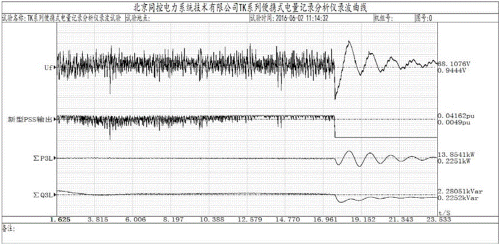
[0076] Taking a certain type of 15kVA dynamic model unit as the implementation object, using the above-mentioned on-site parameter setting method, and comparing whether the unit has PSS or not, the practicability, effectiveness and scientific nature of the specific embodiment of the present invention are further explained.

[0077] In this embodiment, the unit adopts self-shunt excitation mode, and the main rated parameters of the generator are as follows: rated apparent power 15kVA, rated active power 13.5kW, rated machine terminal voltage 380V, direct axis synchronous reactance (unsaturated value) and quadrature axis synchronous The reactance (unsaturated value) is 108.25%.

[0078] 1. Field test of non-compensated hysteresis characteristics of generator excitation system

[0079] The working conditions of the unit during the field test are as fol...


PUM


Abstract

The invention discloses a parameter setting method for a leading phase adaptive type power system stabilizer. In current projects, the conventional PSS (power system stabilizer) parameter setting method mostly adopts a phase correction method by taking an active power input ring as a compensation hysteresis characteristic principle. According to the parameter setting method disclosed by the invention, a leading phase adaptive type power system stabilizer model is adopted, and a corresponding relation between an input rotary speed signal and an active power signal is found by adopting a field test method, and by adopting a classical frequency domain calculation method, a leading phase angle calculation formula of a power-rotary speed axis synthesized vector is obtained; and the corresponding parameters can be set according to non-compensation characteristic of an actual unit through the phase angle calculation of the synthesized vector to enable a synthesized moment to be close to the rotary speed axis. The parameter setting method disclosed by the invention can be used for strengthening oscillation suppression capability of a frequently occurring low-frequency band of a super-huge type alternating current synchronous power grid, and the dynamic stability level of the low-frequency band of the super-huge type alternating current synchronous power grid is improved.

Description

technical field [0001] The invention relates to an on-site parameter setting method for a power system stabilizer, in particular to an on-site parameter setting method for an advanced phase self-adaptive power system stabilizer that uses the synthesis of power-speed variation as input. Background technique [0002] With the steady implementation of the "Thirteenth Five-Year Plan" of the State Grid Corporation of China, my country will form a complex super-large synchronous grid pattern with multiple voltage levels and AC-DC hybrid connections. The increase of the equivalent inertia of the whole network and the change of the start-up mode weaken the damping of the whole network, increase the risk of low-frequency oscillation, and reduce the dynamic stability of the system. [0003] At present, the most widely used method to prevent low-frequency oscillation of the system is the power system stabilizer PSS (Power System Stabilizer). Hysteresis characteristics to achieve the e...

Claims


Application Information

Patent Timeline
Patent Type & Authority Applications(China)
IPC IPC(8): H02J3/24
CPCH02J3/24
Inventor 卢岑岑吴跨宇吴龙沈轶君韩兵黄晓明楼伯良孙维真张锋陆海清房乐
Owner ELECTRIC POWER RES INST OF STATE GRID ZHEJIANG ELECTRIC POWER COMAPNY
Learn More