Intelligent short-circuit protection switching circuit for corrective wave inverter

A short-circuit protection and switching circuit technology, which is applied in the direction of emergency protection circuit devices and electrical components, can solve the problems that the inverter cannot afford non-capacitive loads, has no buffer circuit, and shuts down by mistake, so as to improve the efficiency of inverters with capacitive loads. ability, avoid accidental shutdown or accidental damage, and reduce the effect of circuit cost

Active Publication Date: 2017-05-31
GUANGDONG BESTEK E COMMERCE CO LTD
View PDF4 Cites 3 Cited by
  • Summary
  • Abstract
  • Description
  • Claims
  • Application Information

AI Technical Summary

Problems solved by technology

[0002] In the prior art, common modified wave inverters and AC-to-AC modified wave inverters are directly boosted and filtered before being sent to the inverter circuit without a buffer circuit in between. When the load is resistive, the switch tube of the inverter circuit will generate a peak current dozens of times higher than the normal load, which will usually cause the inverter to not be able to take the non-capacitive load and cause a false shutdown
Moreover, the inverters in the prior art all rely on the performance of the inverter switching device itself to withstand the impact of the current, so it is easy to cause false shutdown or damage to the switching tube, which greatly increases the damage rate and cost of the switching device.

Method used


Image

  • Intelligent short-circuit protection switching circuit for corrective wave inverter
  • Intelligent short-circuit protection switching circuit for corrective wave inverter

Examples


Embodiment Construction

[0018] The present invention will be described in more detail below with reference to the drawings and embodiments.

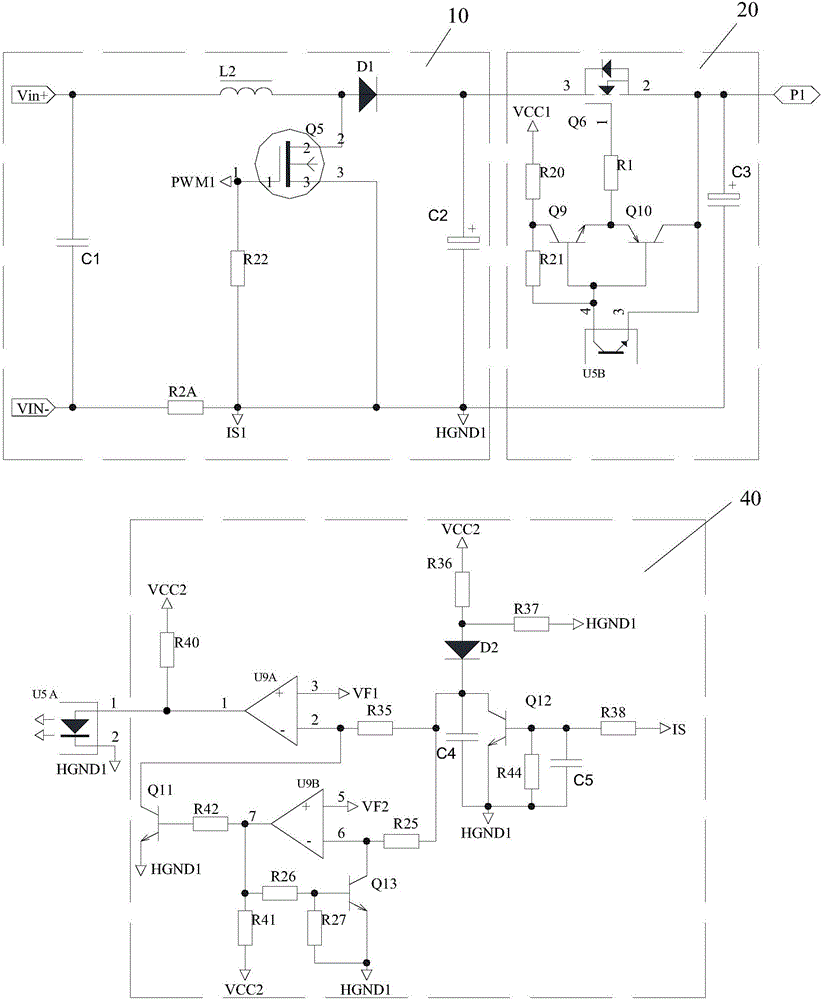
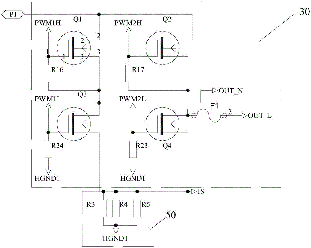
[0019] The invention discloses an intelligent short-circuit protection switch circuit of a modified wave inverter, which combines figure 1 with figure 2 As shown, it includes:

[0020] A PFC boost unit 10 for boosting its input voltage;

[0021] A short-circuit switch unit 20, the input terminal of which is connected to the output terminal of the PFC boost unit 10, and the short-circuit switch unit 20 is used to drive the input terminal and output terminal to conduct or disconnect according to the electrical signal received by the control terminal;

[0022] An inverter unit 30, the input terminal of which is connected to the output terminal of the short-circuit switch unit 20, and the inverter unit 30 is used to invert the voltage output by the short-circuit switch unit 20 into alternating current;

[0023] A current sampling circuit 50 for collecting the current signa...


PUM


Abstract

The invention discloses an intelligent short-circuit protection switching circuit for a corrective wave inverter. The circuit comprises a PFC boosting unit and a short-circuit switching unit. The input end of the short-circuit switching unit is connected with the output end of the PFC boosting unit. The short-circuit switching unit is used for driving the switch-on or switch-off of the input end and the output end based on the electric signals received by the control end of the short-circuit switching unit. The circuit further comprises an inverting unit, a current sampling circuit and an intelligent recognition unit. The intelligent recognition unit is used for receiving the current signals collected by the current sampling circuit, and when the current signals do not surpass a preset value, the intelligent recognition unit sends a switch-on electric signal to the control end of the short-circuit switching unit to make the short-circuit switching unit drive the input end and the output end to switch on. When the current signals surpass the preset value, the intelligent recognition unit sends a switch-off electric signal to the control end of the short-circuit switching unit to make the short-circuit switching unit drive the input end and the output end to switch off. The intelligent short-circuit protection switching circuit for the corrective wave inverter can enhance the capacity of carrying capacitive loads of the inverter, and avoid the mistaken switch-off or mistaken damage of the inverter.

Description

Technical field [0001] The invention relates to a protection circuit of an inverter, in particular to an intelligent short-circuit protection switch circuit of a modified wave inverter. Background technique [0002] In the prior art, common modified sine wave inverters and AC-to-AC modified sine wave inverters are directly boosted and filtered before being sent to the inverter circuit. There is no buffer circuit in between. When the output end of the inverter circuit is impure In the case of resistive load, a peak current that is several tens of times higher than the normal load will be generated on the switch tube of the inverter circuit, which usually causes the inverter to fail to carry a non-capacitive load and cause false shutdown. Moreover, the inverters in the prior art rely on the performance of the inverter switching device itself to withstand the impact of current, so it is easy to cause false shutdown or damage the switching tube, which greatly increases the damage rat...

Claims


Application Information

Patent Timeline
IPC IPC(8): H02H7/122
CPCH02H7/1227
Inventor 侯涛
Owner GUANGDONG BESTEK E COMMERCE CO LTD
Why Eureka
Try Eureka