Eureka AIR delivers breakthrough ideas for toughest innovation challenges, trusted by R&D personnel around the world.

Printed board and radio frequency contact connection structure, connector, contact and printed board

A connection structure and contact piece technology, which is applied in the direction of two-part connection devices, parts of connection devices, fixed/insulated contact members, etc., can solve problems such as poor reliability

Active Publication Date: 2017-05-31
CHINA AVIATION OPTICAL-ELECTRICAL TECH CO LTD
View PDF8 Cites 2 Cited by
  • Summary
  • Abstract
  • Description
  • Claims
  • Application Information

AI Technical Summary

Problems solved by technology

[0004] The purpose of the present invention is to provide a connection structure between a printed board and a radio frequency contact, to solve the problem of poor reliability of the electrical connection between the radio frequency contact and the printed board of the existing printed board and radio frequency contact connection structure; in addition, The purpose of the present invention is also to provide a radio frequency contact used in the above-mentioned printed board and radio frequency contact connection structure and a radio frequency connector using the radio frequency contact; in addition, the purpose of the present invention is to provide a printed circuit board Printed boards used in connection structures between boards and radio frequency contacts

Method used


Image

  • Printed board and radio frequency contact connection structure, connector, contact and printed board
  • Printed board and radio frequency contact connection structure, connector, contact and printed board
  • Printed board and radio frequency contact connection structure, connector, contact and printed board

Examples


Embodiment Construction

[0040] Embodiments of the present invention will be further described below in conjunction with the accompanying drawings.

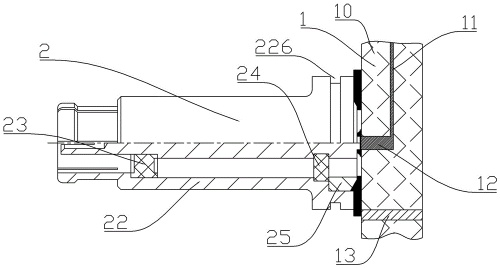
[0041] A specific embodiment of the connection structure between the printed board and the radio frequency contact of the present invention, such as figure 1 As shown, the connection structure between the printed board and the radio frequency contact includes a printed board 1 and a radio frequency contact 2 fixedly assembled on the front side of the printed board.

[0042] The printed board 1 includes a body 10 and a signal conductive layer 11 disposed in the body 10 , and the front side of the body 10 is molded with a signal column 12 electrically connected to the signal conductive layer 11 . The signal column 12 in this embodiment is cast on the front side of the body 10 at a later stage. In other embodiments, the signal column can be integrally formed with the signal conductive layer.

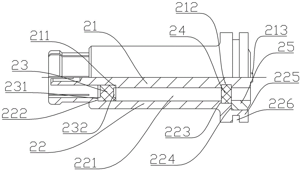
[0043] Such as figure 2 As shown, the radio frequency contact...


PUM


Abstract

The present invention relates to the connector field, especially to a printed board and radio frequency contact connection structure, a connector, a contact and a printed board. The printed board and radio frequency contact connection structure comprises a printed board, the printed board comprises a body and a signal conducting layer arranged in the body, a radio frequency contact is fixed installed at the front side of the body, the radio frequency contact comprise an inner conductor extending along the front and back direction and an outer conductor sleeved at the outer portion of the inner conductor, the body is provided with a signal post electrically connected with the signal conducting layer, and the rear end of the inner conductor is welded and fixed with the signal post. The inner conductor of the radio frequency contact in the printed board and radio frequency contact connection structure is directly welded and fixed on the signal post of the body of the printer board to ensure the reliable electrical connection between the inner conductor and the signal post, improve the reliability of the electrical connection of the inner conductor and the printed board and solve the problem that the reliability of electrical connection between the inner conductor of the current printed board and radio frequency contact connection structure and the printed board is bad.

Description

technical field [0001] The invention relates to the field of connectors, in particular to a connection structure between a printed board and a radio frequency contact piece, a connector, a contact piece, and a printed board. Background technique [0002] RF connector is a relatively common electrical connector, mainly used in occasions that require high-speed and high-quality transmission signals. The RF contact of the RF connector includes an inner conductor and an outer conductor. The inner conductor is coaxially assembled in the outer conductor through a corresponding insulator. During use, the inner conductor is used to transmit signals, and the outer conductor is used to shield external signals. interference to ensure the quality of signal transmission. [0003] The connection between the existing radio frequency contact and the printed board adopts the method of inserting the inner conductor and the printed board, for example, a printed board component disclosed in a ...

Claims


Application Information

Patent Timeline
IPC IPC(8): H01R24/50H01R13/516H01R13/40H01R12/55H01R13/6581
CPCH01R12/55H01R13/40H01R13/516H01R13/6581H01R24/50
Inventor 王学习
Owner CHINA AVIATION OPTICAL-ELECTRICAL TECH CO LTD
Why Eureka
Eureka Blog
Learn More