
Mechanical extrusion-type arc-extinguishing mechanism for power circuit breaker

A circuit breaker and electric power technology, applied in the direction of circuit breaker parts, circuits, electric switches, etc., can solve the problems of power circuit breaker shell damage, loss, ablation contact points, etc., to increase heat storage capacity, increase heat transfer The effect of thermal cross-sectional area

Active Publication Date: 2017-05-31
QINGDAO TOPSCOMM COMM
View PDF2 Cites 2 Cited by
  • Summary
  • Abstract
  • Description
  • Claims
  • Application Information

AI Technical Summary

Problems solved by technology

[0003] A power circuit breaker is a switch that protects the short circuit, overload and leakage of the circuit in the electric power. It can cut off the circuit when the circuit short circuit, overload and leakage occur. The circuit is connected or closed. A high-temperature and high-heat arc will be generated between the moving contact and the static contact. If the arc cannot be exported quickly and extinguished, it will ablate the contact point between the two contacts and cause serious damage to the housing of the power circuit breaker. Large damage, more importantly, the arc will delay the disconnection of the circuit, causing irreparable losses; Short circuit is very important

Method used


Image

  • Mechanical extrusion-type arc-extinguishing mechanism for power circuit breaker
  • Mechanical extrusion-type arc-extinguishing mechanism for power circuit breaker
  • Mechanical extrusion-type arc-extinguishing mechanism for power circuit breaker

Examples


Embodiment Construction

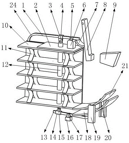
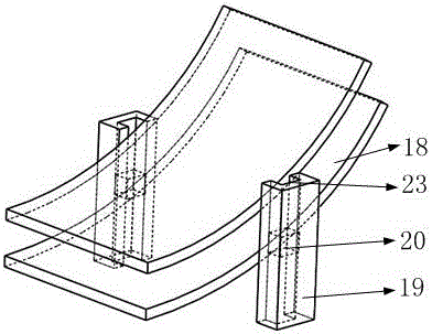
[0015] Such as figure 1 , 2 As shown, it includes a pressure rod 1, a support plate 2, a first trigger rod sliding sleeve 3, a first trigger rod hinge 4, a pressure rod hinge 5, a pressure rod support seat 6, a trigger piece 7, an electric swing rod 8, an electric power fixing End 9, compression plate 10, compression plate spring 11, trigger lever 12, tilting lever 13, second trigger lever sliding sleeve, second trigger lever hinge 15, tilting lever support seat 16, tilting lever hinge 17, bottom guide plate 18, guide plate Guide rail 19, guide plate guide block 20, upper guide plate 21, swing rod rotating shaft 22, guide groove 23, pressure rod elastic end 24, wherein the electric swing rod 8 is installed on the swing rod rotating shaft 22, and one end of the trigger piece 7 is installed on the electric power swing rod 8 , the other end is in contact with the pressure rod 1, the pressure rod 1 is installed on the pressure rod support seat 6 through the pressure rod hinge 5, ...


PUM


Abstract

The invention belongs to the technical field of power circuit breakers, specially relates to a mechanical extrusion-type arc-extinguishing mechanism for a power circuit breaker. The arc-extinguishing mechanism includes a pressure bar, an electrical pendulum rod, an electrical fixed end, compression boards, a trigger lever, a pinch bar, a bottom conductive board and an upper conductive board. When the electrical pendulum rod is separated with the electrical fixed end, an electric arc is produced. Then the electric arc moves to the compression boards. At the same time, the electrical pendulum rod makes the trigger lever to move downward such that the trigger lever provides a downward force to the pinch bar. As a result, the pinch bar moves upwards and provides an upward force to the bottom conductive board. Then the bottom conductive board moves upwards along conductive board guide rails , which makes heat transfer cross-sectional area and heat storage capacity increased such that the electric arc is easier to be extinguished. When the pressure bar begins to move, the elastic end of the pressure bar is deformed. The deformation force produces time-delayed compression on the compression boards. When the electric arc enters into the spaces among the five compression boards, the electric arc is divided into four sections by the compression boards. At the same time, the distances between the compression boards are decreased therefore electric arc energy is released rapidly through the compression boards such that the electric arc is extinguished in short time. The mechanical extrusion-type arc-extinguishing mechanism has good arc extinguishing effect.

Description

[0001] Technical field [0002] The invention belongs to the technical field of electric circuit breakers, in particular to a mechanical extrusion type arc extinguishing mechanism of electric circuit breakers. Background technique [0003] A power circuit breaker is a switch that protects the short circuit, overload and leakage of the circuit in the electric power. It can cut off the circuit when the circuit short circuit, overload and leakage occur. The circuit is connected or closed. A high-temperature and high-heat arc will be generated between the moving contact and the static contact. If the arc cannot be quickly exported and extinguished, it will ablate the contact point between the two contacts and cause serious damage to the power circuit breaker shell. Large damage, more importantly, the arc will delay the disconnection of the circuit, causing irreparable losses; Short circuit is very important. In order to further increase the extinguishing effect on the sudden lar...

Claims


Application Information

Patent Timeline
Patent Type & Authority Applications(China)
IPC IPC(8): H01H9/30
CPCH01H9/30H01H73/18
Inventor 金平娣
Owner QINGDAO TOPSCOMM COMM
Learn More