Detachable voltage transformer

A technology of voltage transformers and transformers, applied in the field of electric power, can solve the problems of prone to ferromagnetic resonance, heavy weight, large size, etc., and achieve the effect of avoiding temperature effects and being easy to disassemble and replace.

Active Publication Date: 2017-05-31
NANTONG YIXUAN IND DESIGN CO LTD
View PDF5 Cites 3 Cited by
  • Summary
  • Abstract
  • Description
  • Claims
  • Application Information

AI Technical Summary

Problems solved by technology

[0002] In the power system, the signals required for voltage metering, measurement and relay protection are mostly provided by electromagnetic transformers. The problems of this transformer are short circuit risk, heavy weight, large volume, and secondary load reflection. Sensitive, prone to ferromagnetic resonance, serious safety hazards
[0003] With the development of digital substations and the needs of smart grid construction, power systems have higher and higher requirements for intelligence and automation of measurement, protection, control and data transmission, and electronic voltage transformers that have emerged as a result have become popular. Research object, in the current medium-voltage system, most electronic voltage transformers adopt the principle of resistance voltage division and resistance-capacity voltage division. Electronic voltage transformers designed with this principle have high heat production efficiency and low load capacity (in mega Europe), low precision, especially after running for a period of time, the error data deviates seriously, exceeding the accuracy level data at the time of delivery, and failing to meet the actual requirements of users
In addition, sealed voltage transformers are not easy to replace parts and repair, and there is an urgent need for voltage transformers that can be easily disassembled

Method used


Image

  • Detachable voltage transformer
  • Detachable voltage transformer
  • Detachable voltage transformer

Examples


Embodiment Construction

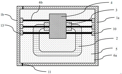
[0029] see figure 1 , the detachable voltage transformer housing of the present invention, comprising:

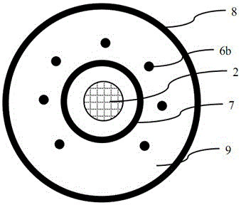
[0030] The metal shell is used to accommodate the transformer, including a left half part 1b and a right half part 1a, the left half part 1b and the right half part 1a can be completely engaged to form a closed metal shell, and the left half part 1b Including a side wall of the metal shell, the right half part 1a includes the top surface, the bottom surface and three side walls of the metal shell, the side wall of the left half part and the side wall of the right half part opposite to the side wall of the left half part There are N protrusions 10 , 13 on the side walls respectively, and the N protrusions 10 , 13 respectively have insertion holes 14 , where N is an integer greater than or equal to 4. The left half 1b has a pin 12 protruding from its end, and the right half 1a has a socket matching the pin 12 (see image 3 , 4 );

[0031] The iron core 2 is in the shape o...


PUM


Abstract

The invention provides a detachable voltage transformer. The detachable voltage transformer comprises a metal shell, an iron core, a primary winding and a secondary winding, multiple heat dispersing material rods and a molding material, the metal shell is used for accommodating the transformer and comprises a left half part and a right half part; the iron core is in a square shape and is placed in the center of the metal shell; the primary winding and the secondary winding twine the iron core corresponding to an inner layer and an outer layer respectively, and are mutually electrically insulated through an insulating material layer; the multiple heat dispersing material rods penetrate the insulating material layer, and are inserted in jack sockets respectively; the metal shell is filled with the molding material, and the iron core, the primary winding and the secondary winding, the heat dispersing material rods are covered by the molding material.

Description

technical field [0001] The invention relates to a transformer in the field of electric power, in particular to a detachable voltage transformer. Background technique [0002] In the power system, the signals required for voltage metering, measurement and relay protection are mostly provided by electromagnetic transformers. The problems of this transformer are short circuit risk, heavy weight, large volume, and secondary load reflection. Sensitive, prone to ferromagnetic resonance, serious safety hazards will occur. At present, with the continuous development of intelligent technology, the power system has developed towards networking, automation and digitalization, and the input signals required by secondary equipment have been significantly reduced, and large-capacity secondary signals are not required. Therefore, this traditional It is difficult for electromagnetic voltage transformers to meet new technical requirements. There is an urgent need for an electronic transfor...

Claims


Application Information

Patent Timeline
IPC IPC(8): H01F38/26H01F27/02H01F27/22
CPCH01F27/02H01F27/22H01F38/26
Inventor 张崇英储微微
Owner NANTONG YIXUAN IND DESIGN CO LTD
Why Eureka
Try Eureka