
A two-degree-of-freedom simulator of a grid rudder aircraft

A simulator and aircraft technology, applied in the field of two-degree-of-freedom simulators, can solve problems such as the two-degree-of-freedom simulator of an aircraft without a grid rudder

Active Publication Date: 2019-03-12
哈尔滨工业大学人工智能研究院有限公司
View PDF5 Cites 0 Cited by
  • Summary
  • Abstract
  • Description
  • Claims
  • Application Information

AI Technical Summary

Problems solved by technology

[0004] The present invention solves the problem of verifying the dynamic model of the grid rudder aircraft and the aerodynamic response under various aerodynamic environments by means of experimental simulation before designing and manufacturing the grid rudder aircraft. Simulator, and there is no problem of a two-degree-of-freedom simulator specially used for a grid rudder aircraft, but a two-degree-of-freedom simulator for a grid rudder aircraft is proposed

Method used


Image

  • A two-degree-of-freedom simulator of a grid rudder aircraft
  • A two-degree-of-freedom simulator of a grid rudder aircraft
  • A two-degree-of-freedom simulator of a grid rudder aircraft

Examples


specific Embodiment approach 1

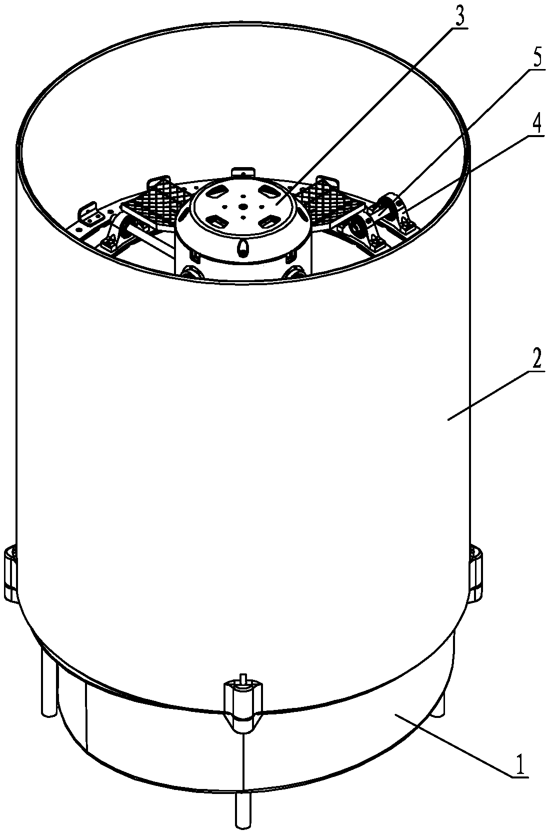
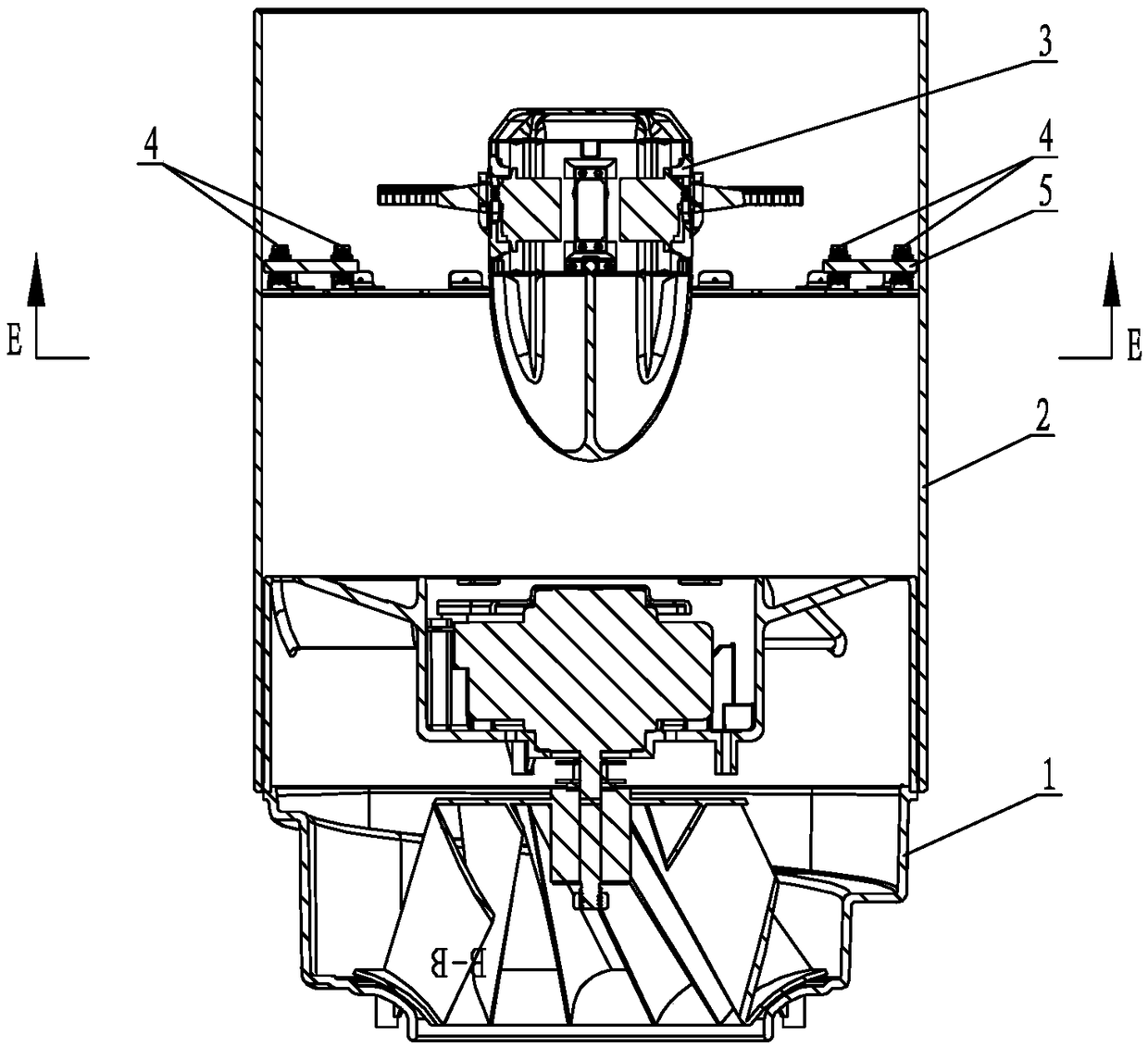
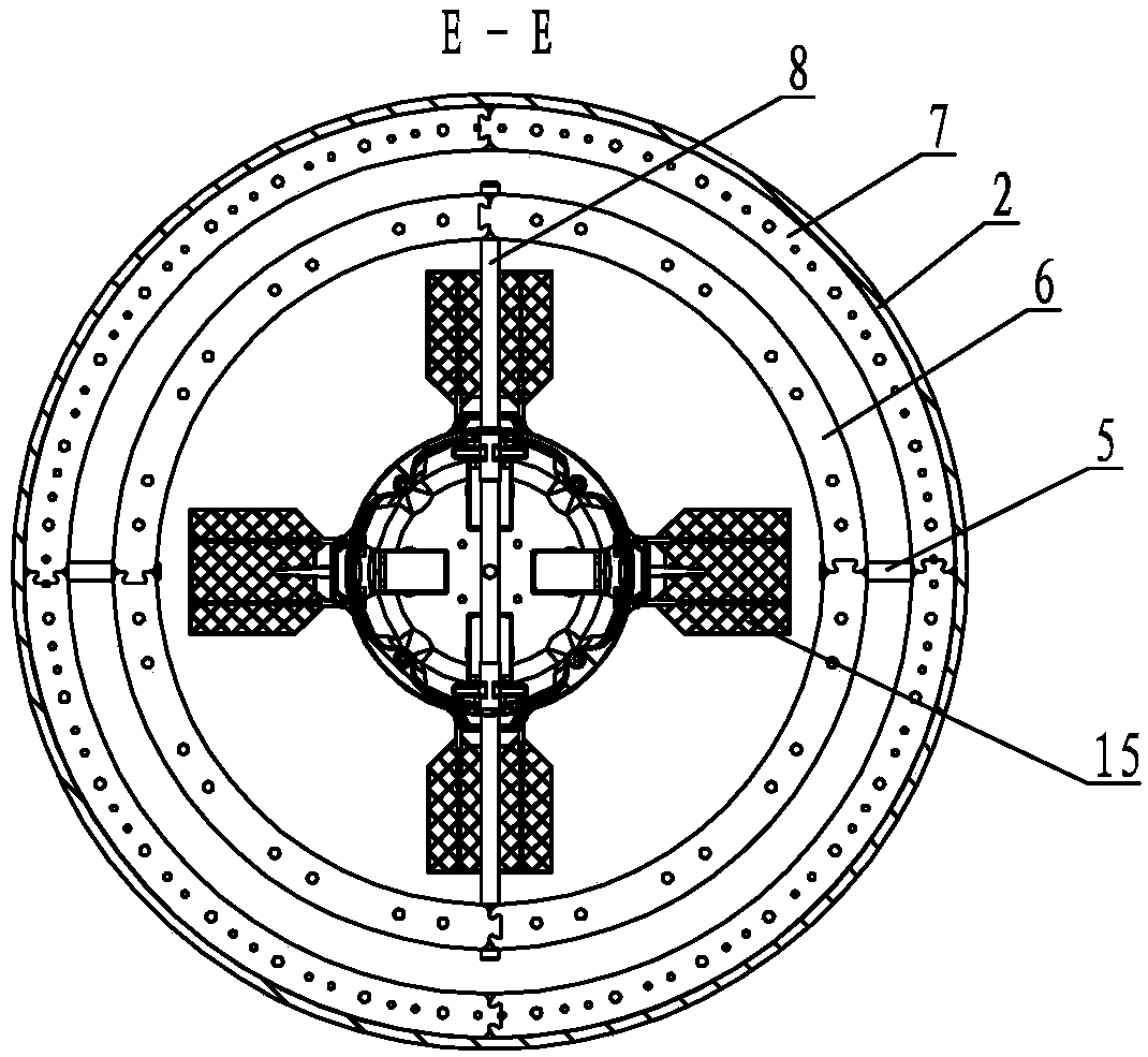
[0018] Specific implementation mode one: combine Figure 1 to Figure 7 Describe this embodiment, this embodiment includes a fan 1, a barrel-shaped air duct 2, a test body 3, a Y swivel 6, an X swivel 7, a long connecting rod 8, two short connecting rods 5 and six bearing housings 4,

[0019] The test body 3 includes a support body 9, a top cover 10, a fairing 11, a counterweight 12, a connecting mechanism 13, four servo motors 14 and four grid rudders 15, and the top cover 10 and the fairing 11 are fixed on the support body respectively. 9, the inside of the fairing 11 is provided with a lead screw 16 along the axial direction, the counterweight 12 is threaded with the lead screw 16, and four servo motors 14 are evenly distributed in the support body 9 along the same circumference, and each The servo motor 14 is fixed on the support body 9, and the four grid rudders 15 are arranged outside the support body 9. The four grid rudders 15 correspond to the four servo motors 14 one ...

specific Embodiment approach 2

[0021] Specific implementation mode two: combination figure 2 and Figure 4 The present embodiment will be described. The thickness of the Y rotary ring 6 and the thickness of the X rotary ring 7 in this embodiment are the same. Other components and connections are the same as those in the first embodiment.

specific Embodiment approach 3

[0022] Specific implementation mode three: combination image 3 and Figure 4 The present embodiment is described. The Y-rotary ring 6 of the present embodiment is formed by sequentially inserting four arc-shaped plates. Other compositions and connections are the same as those in Embodiment 1 or 2.


PUM


Abstract

The invention discloses a two-degree-of-freedom simulator of a grid fin aircraft, and relates to an aircraft simulator. A barrel-shaped air duct is fixedly connected to a fan; an X swivel is arranged along the inner wall of the barrel-shaped air duct; a Y swivel is less than the X swivel in diameter; the Y swivel is arranged in the X swivel; the Y swivel and the X swivel are arranged within a same horizontal plane; four bearing seats are uniformly arranged on the upper end face of the Y swivel along a same circumference; two bearing seats are uniformly arranged on the upper end face of the X swivel along a same circumference; a tested object is arranged in the Y swivel; a long connecting rod runs through a transverse through hole and two passing-through holes and two ends of the long connecting rod are connected to the two opposite bearing seats on the Y swivel; the other two opposite bearing seats on the Y swivel correspond to the two bearing seats on the X swivel one by one; and one end of a short connecting rod is connected to the bearing seats on the Y swivel, while the other end is connected to the bearing seats on the X swivel. The two-degree-of-freedom simulator provided by the invention is used for simulating a pneumatic environment of the grid fin aircraft and verifying a dynamical model and a control method of the grid fin aircraft.

Description

technical field [0001] The invention relates to an aircraft simulator, in particular to a two-degree-of-freedom simulator of a grid rudder aircraft. Background technique [0002] Aircraft is a commonly used control object in control disciplines. Aircraft has characteristics such as nonlinearity and strong coupling, and due to the existence of propellers, aerodynamic factors are introduced into the system. So many scholars in the field of control are keen to study this system and apply the designed control law to the system. [0003] Grid rudders are currently a popular method for controlling the flight attitude of a rocket in atmospheric space. As an unconventional space lifting surface, the grid rudder is a honeycomb structure composed of many thin grid walls embedded in the frame, which can obtain a large lift area while keeping the overall size of the aircraft basically unchanged. At the same time, the hinge moment of the grid rudder is very small, and the power of the...

Claims


Application Information

Patent Timeline
Patent Type & Authority Patents(China)
IPC IPC(8): G09B9/10G09B9/08
CPCG09B9/08G09B9/10
Inventor 张立宪沈俊楠韩睿聂良宁泽鹏张瑞先韩铭昊
Owner 哈尔滨工业大学人工智能研究院有限公司
Learn More