
Two-dimensional constant force mechanism and positioning platform with the mechanism

A two-dimensional plane, constant force technology, applied to the parts and instruments of the instrument, can solve the problems of difficult and high-precision positioning, difficult to manufacture cost, unable to effectively complete the injection, etc., to achieve easy processing and simple structure. Effect

Active Publication Date: 2020-04-14
UNIVERSITY OF MACAU +1
View PDF8 Cites 0 Cited by
  • Summary
  • Abstract
  • Description
  • Claims
  • Application Information

AI Technical Summary

Problems solved by technology

[0008] Existing constant force devices based on flexible mechanisms can only achieve one-dimensional constant force movement, which is far from enough in practical applications
For example, when performing cell injection operations, if the stage can only move in one direction, the injection cannot be effectively completed
And other constant force mechanisms (such as US7677540B1, US6920936B2, CN103438141A) mostly utilize traditional connectors to connect, because traditional connectors have gaps and wear during work, it is difficult to achieve high-precision positioning, and this type of design The structure is more complex, difficult to manufacture and the cost is higher

Method used


Image

  • Two-dimensional constant force mechanism and positioning platform with the mechanism
  • Two-dimensional constant force mechanism and positioning platform with the mechanism
  • Two-dimensional constant force mechanism and positioning platform with the mechanism

Examples


Embodiment Construction

[0037] The two-dimensional constant force mechanism and the positioning platform with the mechanism of the present invention will be described in further detail below in conjunction with the accompanying drawings and specific embodiments, but this is not intended to limit the present invention.

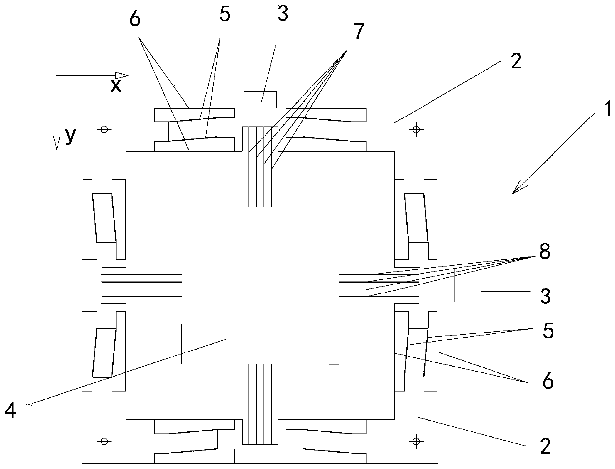
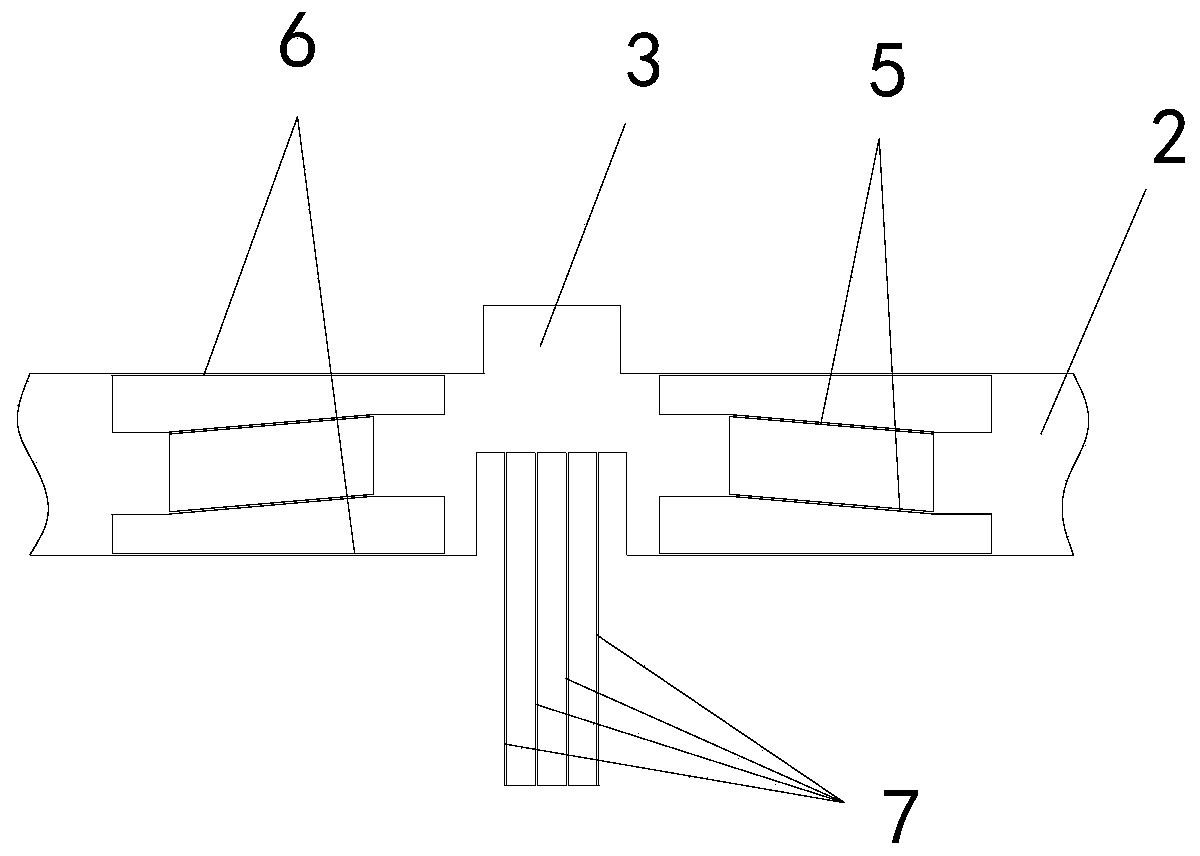
[0038] Such as figure 1 As shown, the present invention provides a two-dimensional constant force mechanism 1, which is used to provide a constant force output in a specified direction in a two-dimensional plane, including a force input terminal 3, a force output terminal 4 and a mechanism for connecting the two and conducting the action. The force-transmitting member of the force, also comprising the base 2, and,

[0039] The force transmission member includes a first transmission member 7 that transmits force to the force output end 4 in the first direction and a second transmission member 8 that transmits force to the force output end 4 in the second direction;

[0040] The force in...


PUM


Abstract

The invention discloses a two-dimensional constant force mechanism and a positioning platform with the mechanism. The two-dimensional constant force mechanism is used for providing constant force output in the assigned direction in a two-dimensional plane and comprises force input ends, a force output end and a force conduction piece used for connecting the force input ends with the force output end and conducting acting force. The two-dimensional constant force mechanism further comprises a base. The force conduction piece comprises a first conduction piece body conducting acting force towards the force output end in the first direction, and a second conduction piece body conducting acting force towards the force output end in the second direction. The force input ends are correspondingly arranged at one end of the first conduction piece body and one end of the second conduction piece body. The force input ends are connected to the base through a first flexible hinge capable of generating negative stiffness and a second flexible hinge capable of generating positive stiffness. The first flexible hinge and the second flexible hinge are connected in parallel and form a quasi zero stiffness system. By the adoption of the two-dimensional constant force mechanism and the positioning platform with the mechanism, constant force output and the two-freedom-degree movement are achieved, the positioning precision is high, and the structure is simple.

Description

technical field [0001] The invention relates to a constant force mechanism, in particular to a two-dimensional constant force mechanism capable of outputting constant force in a specified direction in a two-dimensional plane. The invention also relates to a positioning platform with the constant force mechanism, which belongs to the precision positioning platform in the precision mechanical system, and is mainly used in micro-operation technology (such as scanning probe microscope), bioengineering (cell injection), precise typesetting (3D printing) ) and other fields. Background technique [0002] The precision positioning platform technology based on flexible mechanisms uses flexible hinges instead of traditional linking parts to realize the movement and positioning of parts. It has the advantages of zero friction, zero wear, small impact, simple structure, low cost and strong compatibility. , Positioning system has a wide range of applications. [0003] The constant forc...

Claims


Application Information

Patent Timeline
Patent Type & Authority Patents(China)
IPC IPC(8): G12B5/00G12B3/00
CPCG12B3/00G12B5/00
Inventor 徐青松
Owner UNIVERSITY OF MACAU
Learn More