AutoCAD (Autodesk Computer Aided Design) based plate nesting method

A panel and software technology, applied in the field of panel layout based on AutoCAD, can solve the problems of high cost, waste, cutting waste, etc., and achieve the effect of reducing scrap, waste, and operation difficulty

Active Publication Date: 2017-05-31
瀚隆金属科技(马鞍山)有限公司
View PDF5 Cites 6 Cited by
  • Summary
  • Abstract
  • Description
  • Claims
  • Application Information

AI Technical Summary

Problems solved by technology

[0007] Aiming at the problems of excessive cutting waste, serious waste, and high cost of existing panel cutting, the present invention provides a method for panel layout based on AutoCAD, which can minimize the generation of leftover materials, thereby reducing production costs and saving panels Material

Method used


Image

  • AutoCAD (Autodesk Computer Aided Design) based plate nesting method
  • AutoCAD (Autodesk Computer Aided Design) based plate nesting method
  • AutoCAD (Autodesk Computer Aided Design) based plate nesting method

Examples


Embodiment 1

[0034] In this embodiment, the 45# steel plate of 5000 × 3000 × 5 (mm) is used as raw material, and the area is respectively 14500mm 2 、11300mm 2 、8400mm 2 、7200mm 2 、5600mm 2 、4800mm 2 The plate part to be processed is the object of description and the method of the present invention is described in detail:

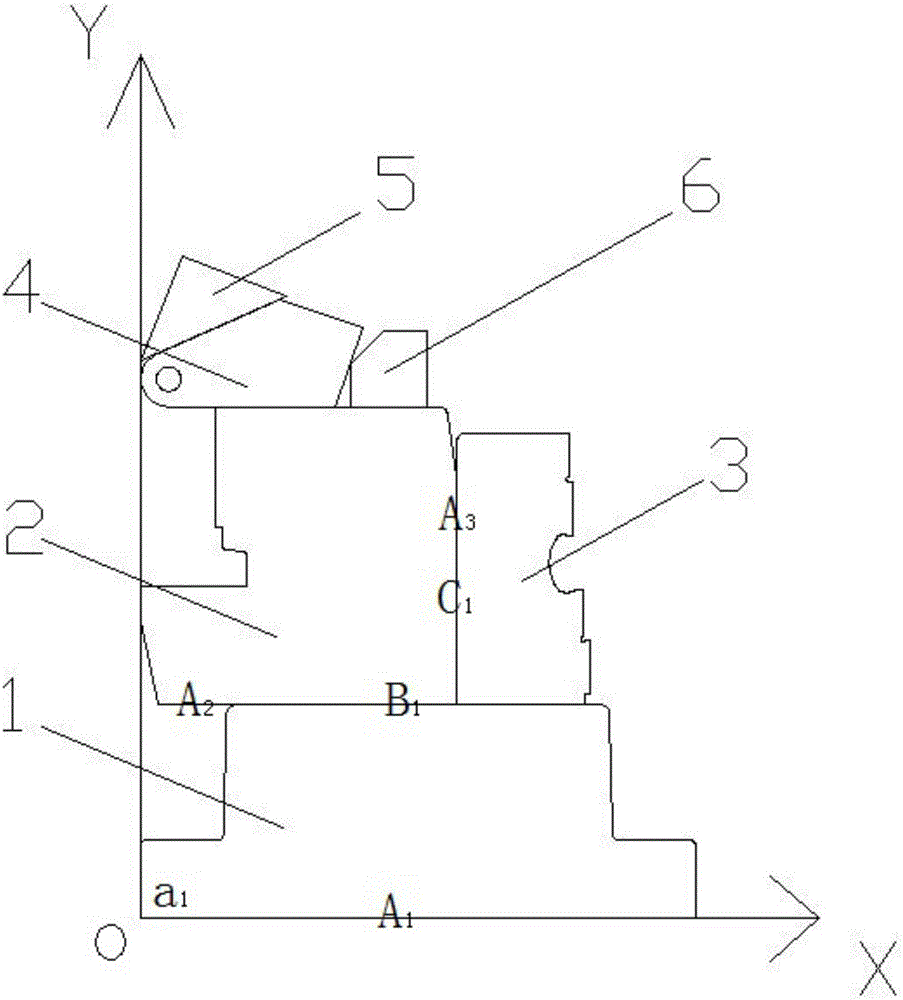
[0035] like figure 1 As shown, a method for panel layout based on AutoCAD includes the following steps:

[0036] Step 1, divide the area to 14500mm according to the size of the area 2 The part number figure one 1, the area is 11300mm 2 The part number is figure two 2, ..., and so on, the area is 4800mm 2 The part number is figure six 6;

[0037] Step 2, draw the figure 1 of the plate part to be processed through the AutoCAD software, specifically take the zero coordinate as the origin, and draw the longest side A of the figure 1 1 one endpoint of the edge a 1 at the origin, place A 1 Place the side on the X or Y axis, and draw a graph 1;

[0038] Step 3, dr...

Embodiment 2

[0047] A method for panel layout based on AutoCAD, which is basically the same as Embodiment 1, the difference is that, considering the loss of corners of parts by cutting, the drawing size of this embodiment leaves a margin of 5-10mm when drawing graphics , to offset the loss generated by the cutting process.

Embodiment 3

[0049] In Example 1, the graphics are first arranged in the order of the graphics area from large to small, and then the layout is carried out according to the method of step 2-step 6, but because the graphics are sorted and drawn according to the order of different sizes, the results of the layout are not the same, so this paper The embodiment increases the step of optimization of material discharge, specifically as follows:

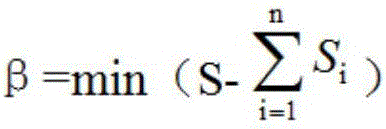
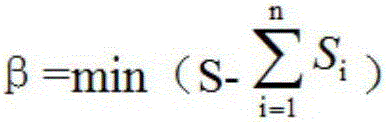
[0050] First calculate the remaining amount of materials β when each graph is drawn in different orders, wherein the remaining amount of materials β is the minimum value after the area of ​​the graphics in Example 1 is arranged from large to small:

[0051]

[0052] where S i Be the area of ​​each figure, n is the number of figures, and the present embodiment is 6, and i is the sequence number of each figure; Therefore

[0053] The parallel line of the Y axis passes through the point with the largest absolute value of x among the coordinate valu...


PUM


Abstract

The invention discloses an AutoCAD (Autodesk Computer Aided Design) based plate nesting method, belongs to the technical field of nesting before cutting of plates and solves the problems of many waste materials, severe waste and high cost of an existing plate cutting method. The method comprises steps as follows: a figure I, a figure II,...and the like of to-be-processed plate parts are drawn by AutoCAD software; the figure II, the figure III, the figure IV,... and the like are sequentially moved along the longest side and the movement stops until any one point in the figures contacts with other figures or X / Y axis, and figure data in a dwg or dxf format is generated; the figure data in the dwg or dxf format is imported into FastCAM software, and codes in an NC format are output through the FastCAM software; the codes in the NC format are input into a numerically-controlled machine tool, and plate cutting is executed. With the adoption of the method, leftover materials can be reduced maximally, so that the production cost is reduced, and plate materials are saved.

Description

technical field [0001] The invention belongs to the technical field of blanking before plate cutting, and in particular relates to a method for blanking blanks based on AutoCAD. Background technique [0002] Before the production and processing of the products, the factory needs to carry out the budget layout work on the panel materials to determine the quantity of raw materials consumed. Due to the different shapes of the parts, currently the layout is carried out by manual experience. The size of the discharge material is enlarged, resulting in a serious waste of raw materials, and the utilization rate of leftover materials is very low, so the production cost is extremely high. In the prior art, there are also methods of nesting using software, such as: [0003] Chinese Patent Application No. 201210568985.9, the patent document published on April 17, 2013, discloses an automatic and rapid discharge method for a sponge cutting machine. The steps are as follows: a. Base map...

Claims


Application Information

Patent Timeline
IPC IPC(8): G05B19/408
CPCG05B19/4083G05B2219/35356Y02P80/40Y02P90/02
Inventor 孙禄善夏华洋
Owner 瀚隆金属科技(马鞍山)有限公司
Why Eureka
Try Eureka