
Quartz clock type timer movement

A technology for timers and quartz clocks, which is applied to electronically indicate time, instruments, clocks and other directions, which can solve problems such as interfering with users' study and work, short prompting bells, and large travel time errors of mechanical movements.

Active Publication Date: 2017-05-31
HANGZHOU JINGCHENG SANHE TIMER IND
View PDF8 Cites 11 Cited by
  • Summary
  • Abstract
  • Description
  • Claims
  • Application Information

AI Technical Summary

Problems solved by technology

[0002] Most of the existing timers use mechanical movements, so there are the following disadvantages: before use, the scale cover should be rotated a circle (the spring of the mechanical movement should be tightened), and then the scale cover should be reversely rotated to the timing position. Many first-time users will not use the above method, but directly turn the scale cover to the timing position, resulting in too short a reminder ring; during the timing process, the mechanical movement will continuously produce ticking sounds, and these noises are likely to interfere with the user's learning and work, so it cannot be used in a quiet environment; the travel time error of the mechanical movement is large

Method used


Image

  • Quartz clock type timer movement
  • Quartz clock type timer movement
  • Quartz clock type timer movement

Examples


Embodiment Construction

[0029] The present invention will be further described below in conjunction with the accompanying drawings of the specification, but the present invention is not limited to the following embodiments.

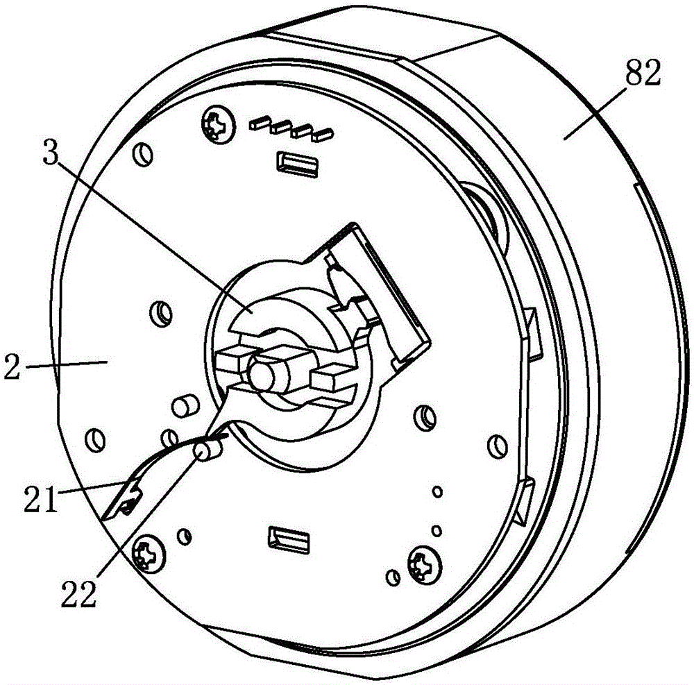
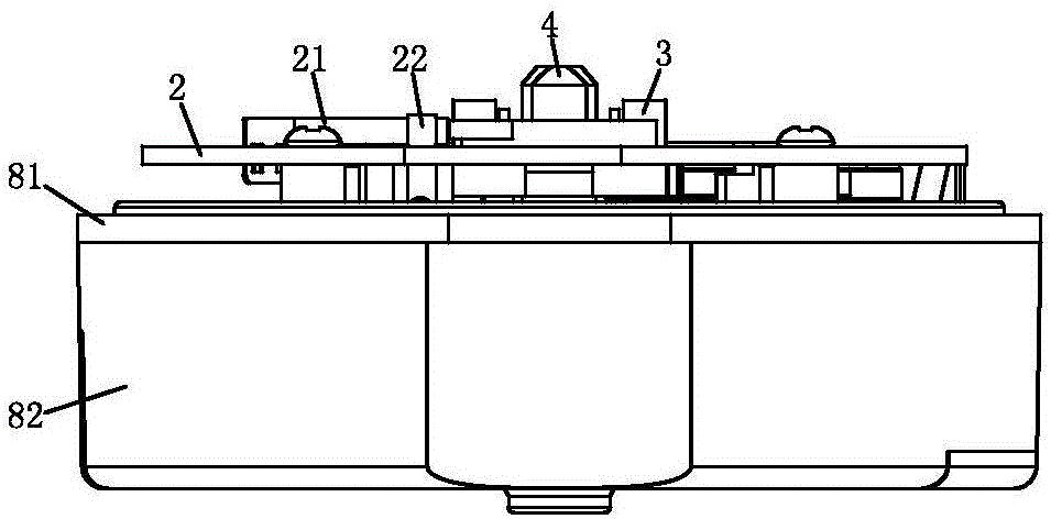
[0030] Such as Figure 8 As shown, the quartz clock timer movement includes a casing, a quartz movement 1, a PCB board 2, a center output wheel assembly, a walking wheel 3, a sounding component (preferably a horn) 9, and a limit component. The housing includes a base 82 and an upper cover 81. The bottom of the base is provided with a battery compartment 83, a screw hole 84 and a number of positioning holes 85. The battery installed in the battery compartment is used to supply power to the quartz movement and the PCB board. The quartz movement, the sound generating component, and the central output wheel assembly are packaged in a housing, the sounding component is arranged at the bottom of the quartz movement, and the central output wheel assembly is arranged on the top of the quar...


PUM


Abstract

The invention relates to a quartz clock type timer movement. The timer movement needs to have the advantages of being convenient to operate, low in noise and accurate in timing. According to the technical scheme, the quartz clock type timer movement is characterized in that the time movement comprises a shell, a quartz movement, a sound producing part and a center output wheel assembly driven by the quartz movement are arranged in the shell, a PCB and a walking-through wheel driven by the center output wheel assembly are arranged on the top of the shell, and a battery bin is arranged at the bottom of the shell; a spring piece and a switching column are arranged on the PCB, and the walking-through wheel is provided with a driving lever for forcing the spring piece to be bent to make contact with the switching column.

Description

Technical field [0001] The invention relates to a timing device, specifically a timer. Background technique [0002] Most of the existing timers use mechanical movements, so they have the following shortcomings: before use, rotate the scale cover one turn (tighten the mainspring of the mechanical movement), and then rotate the scale cover to the timing position in reverse. Many first-time users will not use the above method, but directly turn the scale cover to the timing position, resulting in the warning bell is too short; the mechanical movement will continue to produce ticking sounds during the timing process, these noises will easily interfere with the user's learning and It works, so it cannot be used in a quiet environment; the time error of the mechanical movement is relatively large. Summary of the invention [0003] The purpose of the present invention is to overcome the deficiencies in the above-mentioned background technology and provide a quartz clock-type timer move...

Claims


Application Information

Patent Timeline
Patent Type & Authority Applications(China)
IPC IPC(8): G04F3/02
CPCG04F3/02G04C21/28G04C3/008
Inventor 池汉军
Owner HANGZHOU JINGCHENG SANHE TIMER IND
Learn More