
In-formation radar far field prediction method taking regard of near sea surface atmosphere environment influence

A technology of atmospheric environment and prediction methods, applied in radio wave measurement systems, instruments, etc., can solve problems such as extremely complex electromagnetic interference between platforms, affecting naval combat missions, and complex electromagnetic environments

Inactive Publication Date: 2017-05-31
CHINA SHIP DEV & DESIGN CENT
View PDF4 Cites 7 Cited by
  • Summary
  • Abstract
  • Description
  • Claims
  • Application Information

AI Technical Summary

Problems solved by technology

With the increase of the transmission power of various radars, the expansion of the frequency spectrum, and the continuous increase in the number of frequency equipment, the electromagnetic environment in the maritime formation is becoming more and more complex, and the electromagnetic interference between platforms has become extremely complicated.
Otherwise, once there is electromagnetic interference, it is bound to destroy the overall combat capability of the formation and seriously affect the navy's implementation of combat missions

Method used


Image

  • In-formation radar far field prediction method taking regard of near sea surface atmosphere environment influence
  • In-formation radar far field prediction method taking regard of near sea surface atmosphere environment influence
  • In-formation radar far field prediction method taking regard of near sea surface atmosphere environment influence

Examples


Embodiment Construction

[0066] The technical solution of the present invention will be described in detail below with reference to the drawings and examples.

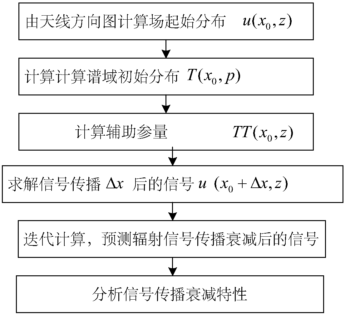
[0067] The method for predicting the far-field radar in a formation considering the influence of the atmospheric environment of the offshore surface of the present invention includes the following steps:

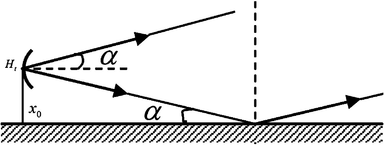
[0068] (1) According to figure 1 The shown schematic diagram of the formation radar reflecting on the sea surface, the installation height position of the radiation source radar in the formation is obtained, the radiation source pattern function in the formation is A(α), and the antenna erection height is H t , Calculate the radar at x 0 The initial field distribution in the z direction along the height direction at the position.

[0069] (2) Establish the atmospheric refractive index model of the offshore surface according to the characteristics of the radar signal;

[0070] Considering that the propagation of radar electromagnetic signals within t...


PUM


Abstract

The invention discloses an in-formation radar far field prediction method taking regard of near sea surface atmosphere environment influence. The method comprises steps that (1), according to the in-formation radiation source radar mounting height position, radar initial field distribution is calculated; (2), according to radar signal characteristics, a near sea surface atmosphere refractivity model is established; (3), according to the relative position of a radiation source radar and an observation point and the atmosphere refractivity model on a formation radar propagation path, a formation radar electromagnetic signal forward propagation model is established, and propagation attenuation factors taking regard of near sea surface atmosphere influence are calculated through utilizing a two-dimensional parabola algorithm; and (4), lastly, in combination with shipborne radar directional diagram characteristics, an electromagnetic environment of the in-formation far field is solved, and prediction field intensity of the observation point is calculated. The method is advantaged in that radar far field intensity at the observation point is predicted through establishing the electromagnetic signal forward propagation model taking regard of influence of near sea level rough sea surface reflection and near sea surface atmosphere environment parameters, environment parameters are provided for formation electromagnetic compatibility analysis, and the method is applicable to electromagnetic interference analysis.

Description

Technical field [0001] The invention belongs to the field of ship electromagnetic compatibility prediction, and specifically relates to a far-field prediction method for radar in formations considering the influence of the atmospheric environment on the offshore surface. Background technique [0002] With the development of new naval equipment, ship formations have become the main use of naval ships to give full play to the combat capabilities of various ships. With the increase in the transmission power of various radars, the expansion of the frequency spectrum, and the continuous increase in the number of frequency equipment, the electromagnetic environment in the maritime formation is becoming more and more complicated, and the problem of electromagnetic interference between platforms has become extremely complicated. Otherwise, once there is electromagnetic interference, it will inevitably destroy the overall combat capability of the formation and seriously affect the naval's...

Claims


Application Information

Patent Timeline
IPC IPC(8): G01S7/40
CPCG01S7/40
Inventor 刘其凤吴为军谭辉奚秀娟倪超
Owner CHINA SHIP DEV & DESIGN CENT
Learn More