Environment monitoring system based on micro power wireless communication technology

A micro-power wireless and environmental monitoring technology, applied in measurement devices, instruments, etc., can solve the problems of complex construction, heavy maintenance workload, and complicated implementation, and achieve the effect of convenient installation and improved system stability.

Inactive Publication Date: 2017-05-31
BEIJING YIJING YOUZHI ENVIRONMENT TECH CO LTD
View PDF5 Cites 4 Cited by
  • Summary
  • Abstract
  • Description
  • Claims
  • Application Information

AI Technical Summary

Problems solved by technology

[0004] (1) For a room with a large area, it is impossible to control the environmental quality from the system level: since the detection equipment operates independently, it can only monitor the environmental quality near the equipment. Even if multiple equipment is arranged, each equipment is independent It is running, the data cannot be displayed in a centralized manner, the real-time effect is poor, and the indoor air quality cannot be monitored and analyzed from the system level
Can not meet the requirements of the environment
Each module supplied by the device is usually non-low power consumption, so the standby time is short
[0005] (2) For air quality monitoring equipment based on RS485 communication, usually a single device can only monitor a single indicator, and the communication uses 485 network communication, and the monitoring indicators of each device are relatively single
[0006] This way of monitoring indicators is relatively simple. Usually, a single device can only monitor a certain fixed indicator, and does not have the function of a device that can detect multiple indicators. Due to the use of 485 communication, it is necessary to wire the communication lines and power supply circuits.
The construction is extremely complicated and the installation is inconvenient
If multiple indicators such as indoor temperature and humidity, formaldehyde, and particulate matter are detected at the same time, multiple sets of detection equipment need to be deployed, and the implementation is extremely complicated, resulting in a large workload for later maintenance

Method used


Image

  • Environment monitoring system based on micro power wireless communication technology
  • Environment monitoring system based on micro power wireless communication technology

Examples


Embodiment Construction

[0028] Embodiments of the present invention are described in detail below, examples of which are shown in the drawings, wherein the same or similar reference numerals designate the same or similar elements or elements having the same or similar functions throughout. The embodiments described below by referring to the figures are exemplary and are intended to explain the present invention and should not be construed as limiting the present invention.

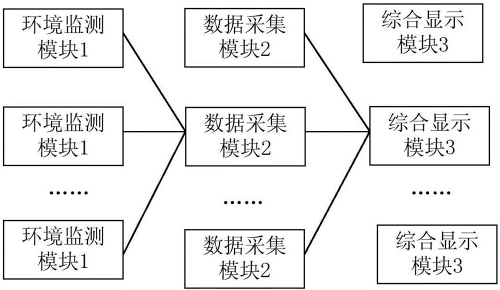
[0029] Usually, large sites with strict environmental requirements are mostly composed of multiple large areas, and each area needs to deploy multiple monitoring points according to the monitoring model. The data of each monitoring point needs to be displayed in a centralized manner, which can reflect the comprehensive environmental quality of large production plants from the perspective of macro and onlookers. This is mostly the case in important places such as large laboratories, pharmaceutical factories, pharmacies, drug store...


PUM


Abstract

The invention provides an environment monitoring system based on micro power wireless communication technology. The system comprises an environmental monitoring module which is used for collecting air quality data of an equipment nearby area after receiving a task instruction of a data acquisition module and sending the air quality data to the data acquisition module through the micro power wireless communication technology, wherein an Ad-Hoc network is realized by multiple sensors in the environmental monitoring module through the micro power wireless communication networking technology, and multiple communication channels are supported. Each data acquisition module receives and stores the air quality data of a corresponding communication channel. An integrated display module is used for analyzing the air quality data from each data acquisition module, according to the differences of monitored areas and equipment, the data is displayed to a user in a visual form, and the user monitors and evaluates the air quality of an environment where the equipment is located. According to the system, the rapid installation deployment and centralized display of large space indoor environment monitoring are solved from a system level.

Description

technical field [0001] The invention relates to the technical field of wireless communication and environment monitoring, in particular to an environment monitoring system based on micro-power wireless communication technology. Background technique [0002] At present, there are many types of indoor environment monitoring products on the market. Most of them are a single device that can detect single or multiple indicators such as carbon dioxide concentration, particulate matter, VOC, formaldehyde, temperature and humidity in the air. The product is usually powered by battery or USB, has its own LCD screen, and operates independently. [0003] However, the indoor environment monitoring products in the prior art have the following problems: [0004] (1) For a room with a large area, it is impossible to control the environmental quality from the system level: since the detection equipment operates independently, it can only monitor the environmental quality near the equipmen...

Claims


Application Information

Patent Timeline
Patent Type & Authority Applications(China)
IPC IPC(8): G01D21/02
CPCG01D21/02
Inventor 李振
Owner BEIJING YIJING YOUZHI ENVIRONMENT TECH CO LTD
Why Eureka
Try Eureka