
Array polarization navigation sensor

A polarized navigation and sensor technology, applied in navigation, surveying and mapping, navigation, instruments, etc., can solve the problems of low spatial resolution and few sampling points of point source sensors, achieve large photosensitive area, reduce external stray light interference, The effect of reducing the impact

Active Publication Date: 2017-05-31
BEIHANG UNIV
View PDF5 Cites 8 Cited by
  • Summary
  • Abstract
  • Description
  • Claims
  • Application Information

AI Technical Summary

Problems solved by technology

Three-channel polarization navigation sensor, patent number 20130380079.0, designed a three-channel polarization sensor, using photodiodes as photosensitive chips, point source sensors with fewer sampling points and lower spatial resolution

Method used


Image

  • Array polarization navigation sensor
  • Array polarization navigation sensor
  • Array polarization navigation sensor

Examples


Embodiment Construction

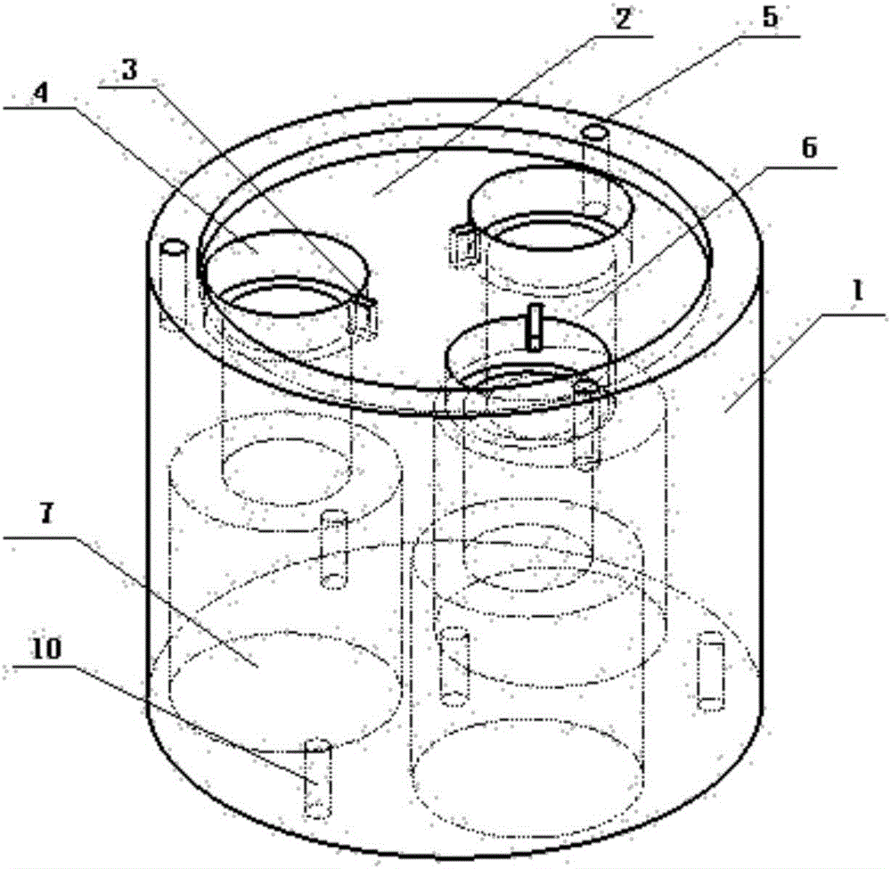
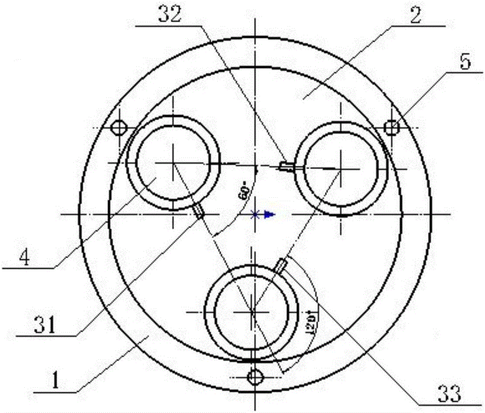
[0010] Such as figure 1 , 2 As shown, the array polarization navigation sensor is mainly composed of an optical lens structure (1), a photoelectric detection module (8) and an information solving circuit (9); the optical lens structure (1) includes a filter slot (2), Polarizer grooves (4) and optical path channels (6) etc.; the optical lens structure has three polarizer grooves (4), and each polarizer groove edge has a groove (3), such as image 3 As shown, they are respectively named as the first indicating groove (31), the second indicating groove (32) and the third indicating groove (33), and the first indicating groove 31 is selected as the reference direction, then the first indicating groove (31), the second indicating groove The second indicator groove (32) and the third indicator groove (33) differ from the reference direction by 0°, 60°, and 120° respectively, and are used to indicate the installation direction of the polarizer; the channel (7) is connected below the...


PUM


Abstract

The invention discloses an array polarization navigation sensor, comprising an optical lens structure, a photoelectric detection module and an information resolving circuit, wherein the optical lens structure comprises an optical filter groove, polarizing film grooves and a light path channel; the optical lens structure is provided with three polarizing film grooves used for indicating the installation direction of the polarizing films; a passage is connected to the bottom of the light path channel, the photoelectric detection module is a circuit board arranged with three CMOS sensors, and is fixedly connected with the optical lenses via a retaining screw; and the photoelectric detection module transmits signals to the information resolving circuit via a connector assembly for resolving navigation information. The array polarization navigation sensor is mainly used to solve the problem of few sampling sites and insufficient utilization of sky polarization information of the existing polarization navigation, and has the advantages of high precision, high integration level and reliable performance.

Description

technical field [0001] The invention relates to a polarization navigation sensor, and relates to a design of an array polarization navigation sensor, which can be applied to the navigation of carriers such as drones, vehicles, and ships, and improves the accuracy and autonomy of the navigation system. Background technique [0002] Scientists have discovered that creatures such as sand ants in nature can use the rich navigation information contained in the atmospheric polarization distribution pattern to achieve navigation and positioning. Polarized light navigation, as a new bionic navigation method, has the advantages of passive, no radiation, and strong autonomy, and has received extensive attention from scientists. Polarized light navigation can be widely used in the navigation of drones, vehicles, ships and other carriers, effectively improving the autonomy and reliability of the carrier's navigation system. The development of high-precision polarization navigation sens...

Claims


Application Information

Patent Timeline
Patent Type & Authority Applications(China)
IPC IPC(8): G01C21/00
CPCG01C21/00
Inventor 郭雷王纲张霄杨健牛奔
Owner BEIHANG UNIV
Learn More