
A device for solving local uneven settlement of pipelines by using two rotary compensators

A technology of rotating compensator and pipeline, applied in the direction of pipeline laying and maintenance, pipe/pipe joint/pipe fitting, mechanical equipment, etc., can solve the problems of uneven settlement, pipeline cracking, etc. The effect of saving engineering investment

Active Publication Date: 2018-12-04
武汉德威工程技术有限公司
View PDF7 Cites 0 Cited by
  • Summary
  • Abstract
  • Description
  • Claims
  • Application Information

AI Technical Summary

Problems solved by technology

[0005] Although there is a compensator used in the prior art to compensate for the displacement caused by thermal expansion and contraction of the pipeline, in actual operation, the following problems still occur in the thermal pipeline: the thermal pipeline will be uneven due to foundation or geological reasons during operation. The settlement of the pipeline may cause the pipeline to be pulled apart

Method used


Image

  • A device for solving local uneven settlement of pipelines by using two rotary compensators
  • A device for solving local uneven settlement of pipelines by using two rotary compensators
  • A device for solving local uneven settlement of pipelines by using two rotary compensators

Examples


Embodiment 1

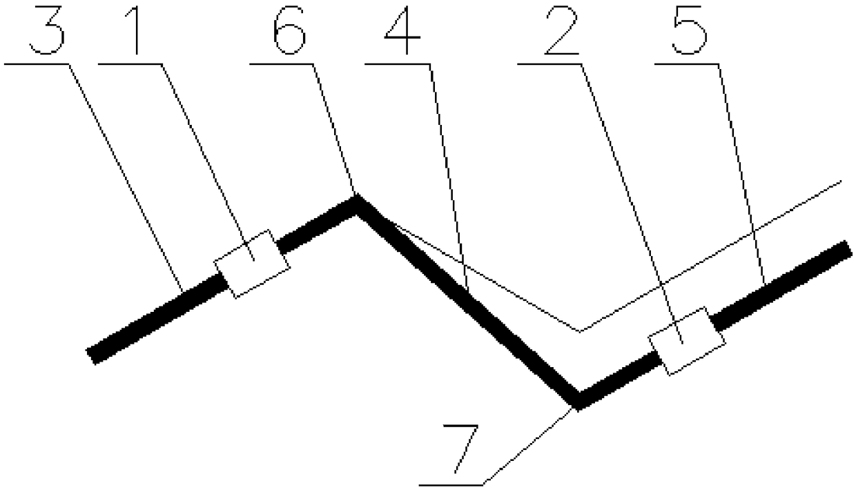
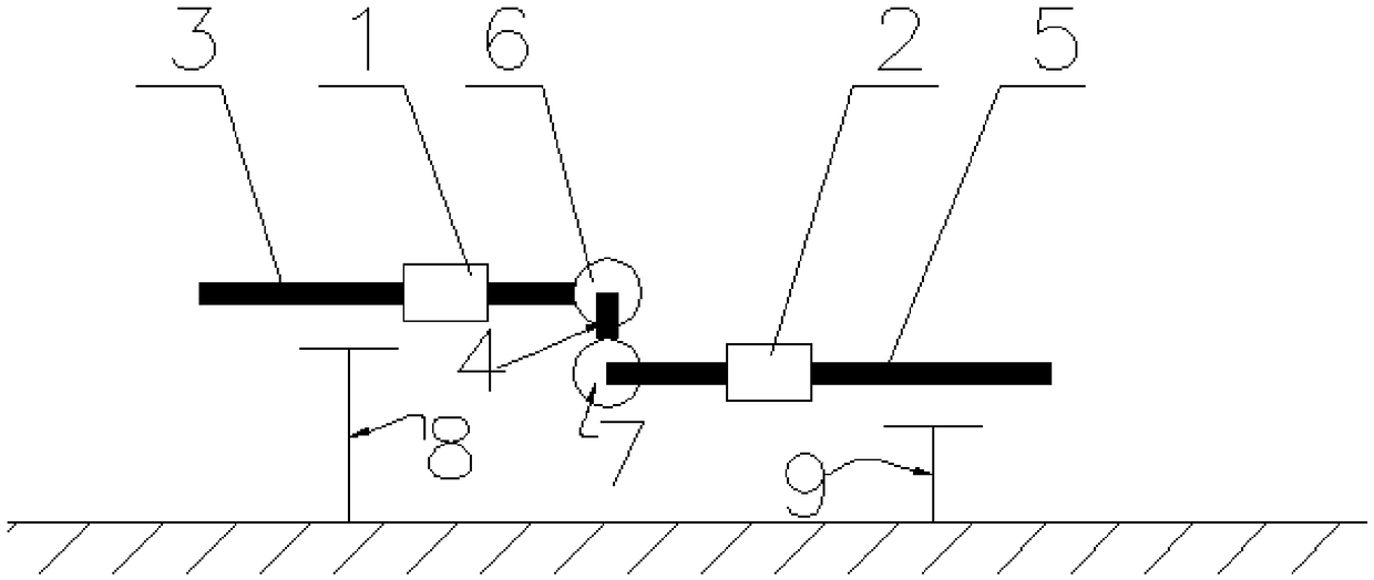
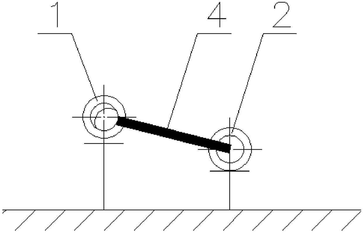
[0031] Such as figure 1 , figure 2 and image 3 Shown: The device adopts two rotary compensators to solve the local uneven settlement of the pipeline. The axes of the first horizontal pipeline 3 and the second pipeline 5 are parallel. The first pipeline 3 is equipped with the first rotary compensator 1 and the second pipeline 5 The second rotary compensator 2 is installed on it, and the axes of the first rotary compensator 1 and the second rotary compensator 2 are guaranteed to be parallel. One end of the first pipe 3 is connected to the short pipe 4 through the first elbow 6 , and one end of the second pipe 5 is connected to the short pipe 4 through the second elbow 7 . Therefore, it is ensured that the first pipeline 3 communicates with the second pipeline 5 .

[0032] The first support 8 with support function is installed under the first pipeline 3, and the first support 8 is installed on the ground surface; the second support 9 with support function is installed at the...

Embodiment 2

[0035] Such as Figure 6 and image 3 As shown in the figure, two rotary compensators are used to solve the problem of local non-subsidence of the pipeline. The horizontal first pipeline 3 and the second pipeline 5 are parallel in axis. The second rotary compensator 2 is installed, and the axes of the first rotary compensator 1 and the second rotary compensator 2 are guaranteed to be parallel. One end of the first pipe 3 is connected to the short pipe 4 through the first elbow 6 , and one end of the second pipe 5 is connected to the short pipe 4 through the second elbow 7 . Therefore, it is ensured that the first pipeline 3 communicates with the second pipeline 5 .

[0036] A method for solving local uneven settlement of pipelines by using two rotating compensators, the method includes the following steps:

[0037] 1) Install two pipes and ensure that the axes of the two pipes are parallel to each other;

[0038] 2) Install rotary compensators on the two pipes, and ensure ...


PUM


Abstract

The invention discloses a device for solving the problem of local differential settlement of a pipeline through two rotating compensation devices. The device comprises a first pipeline body (3) and a second pipeline body (5). The first rotating compensation device (1) is mounted on the first pipeline body, and the second rotating compensation device (2) is mounted on the second pipeline body. The axes of the first pipeline body and the second pipeline body are parallel, and the axes of the first rotating compensation device and the second rotating compensation device are parallel. The first pipeline body is connected with the second pipeline body through a short pipe (4). By arranging a heating pipeline in the mode, the problem of differential settlement of the pipeline can be effectively solved; and through rotation of the rotating compensation devices, the short pipe and a bend form a force arm, accordingly, free rotation in a pipeline constraint range is achieved, and free settlement of the two pipeline bodies in a designed range is ensured.

Description

technical field [0001] The invention relates to a device for solving local uneven settlement of pipelines, in particular to a device for solving local uneven settlement of pipelines by using two rotating compensators, belonging to the technical field of thermal pipelines Background technique [0002] Heat pipes, also known as heat pipe networks, start from the boiler room, direct-fired machine room or heating center, and lead from the heat source to the heat supply pipes at the thermal entrance of the building. Multiple heat supply pipes form a pipe network. [0003] During the laying of thermal pipelines, the main accessories include compensators, hangers and valves. The compensator is mainly used to solve the thermal displacement caused by the thermal expansion and contraction of the pipeline in the thermal pipeline; the support and hanger mainly plays a supporting role, and generally adopts a sliding support or a rigid hanger; the valve is mainly used in the main line of ...

Claims


Application Information

Patent Timeline
Patent Type & Authority Patents(China)
IPC IPC(8): F16L1/024
CPCF16L1/024F16L1/0246
Inventor 杨天松徐斌王湘红邱杰杰樊友田曾雄伟林啸
Owner 武汉德威工程技术有限公司
Learn More