
Sliding Vane Compressor

A compressor and sliding vane technology, applied in the field of sliding vane compressors, can solve the problems of weak journals, lack of oil on the sliding vane blade surface, increased internal energy consumption, etc., to achieve simple surface roughness, reduce processing costs, The effect of alleviating high pressure shock

Active Publication Date: 2018-09-21
盐城中德劲博机电有限公司
View PDF6 Cites 0 Cited by
  • Summary
  • Abstract
  • Description
  • Claims
  • Application Information

AI Technical Summary

Problems solved by technology

The existing vane compressors have the following disadvantages: (1) The chute in the rotor is linear. In the past, the relative radial value of the chute and the journal must be increased to meet the demand of the displacement. , in order to ensure the smoothness of the entire structure, the aesthetics of the appearance, etc., the journals at both ends of the rotor are reduced, resulting in weak journals at both ends of the rotor that are easy to break
(2) In the past, there was no oil groove in the chute on the rotor, and it was difficult to lubricate between the blade face of the blade and the rotor. Its lubrication channel is that after the two sides of the blade are lubricated, the excess oil flows to the blade face of the blade, which belongs to the second Level oil supply lubrication, which requires sufficient oil. In the case of a slight shortage of oil supply, there is a danger of oil shortage on the blade surface of the slide vane. big impact
(3) During use, high pressure shocks are easily formed at both ends of the chute, causing its temperature to rise
(4) In the past, there was a direct fit between the end cover and the rotor. During the start-up process of the piston machine, before the lubricating oil pressure was fully established, the rotor rotated and the end cover was fixed. There was contact between the end face of the rotor and the end cover. The state of dry friction will inevitably cause wear. Once there is a gap between the worn rotor and the end cover, it will cause leakage, resulting in a decrease in the displacement index of the compressor and an increase in internal energy consumption. The current measure to prevent wear is to use wear resistance Good materials, but the end cover is a large piece, the cost will be high if the material with good wear resistance is used, and the matching surface between the end cover itself and the rotor is limited by the processing conditions, and the accuracy is difficult to guarantee
(5) When the intake valve is not working properly, when the machining accuracy of the sliding vane or the rotor is not up to the standard or wear occurs under the state of oil loss, the intake air volume is greater than the exhaust volume, and pressure will be generated in the internal suction and exhaust passages The phenomenon of sharp rise, the oil and gas circuit is not working smoothly, resulting in uneven force on the sliding plate during movement

Method used


Image

  • Sliding Vane Compressor
  • Sliding Vane Compressor
  • Sliding Vane Compressor

Examples


Embodiment Construction

[0019] The specific content of the present invention will be described in detail below in conjunction with the accompanying drawings and specific embodiments.

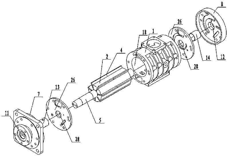
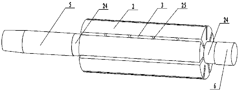
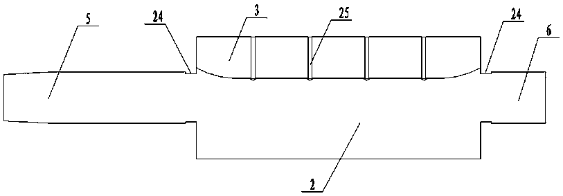
[0020] Such as figure 1 , figure 2 , image 3 , Figure 4 , Figure 5 , Figure 6 , Figure 7 , Figure 10As shown, the sliding vane compressor includes: a cylinder block 1 as a stator, a rotor 2 arranged in the cylinder block 1, a number of slide grooves 3 are evenly arranged on the middle part of the rotor 2, and the sliding vanes 4 slide In the chute 3 which cooperates with it, a front journal 5 is provided at the front end of the rotor 2, a rear journal 6 is provided at the rear end of the rotor 2, and a rear journal 6 is provided at the front end of the cylinder block 1. There is a front end cover 7, and a rear end cover 8 is arranged at the rear end of the cylinder body 1, and a number of end cover fixing holes 9 are evenly arranged on the rear end cover 8 and the front end cover 7 respectively. A number...


PUM


Abstract

The invention discloses a slide vane compressor more stable in work. The slide vane compressor comprises an air cylinder body serving as a stator, and a rotor arranged in the air cylinder body. The middle of the rotor is uniformly provided with a plurality of slide grooves. Slide vanes are slidably arranged in the slide grooves matched with the slide vanes. The front end of the rotor is provided with a front shaft neck, and the rear end of the rotor is provided with a rear shaft neck. The front end of the air cylinder body is provided with a front end cover, and the rear end of the air cylinder body is provided with a rear end cover. The front end cover and the rear end cover are each evenly provided with a plurality of end cover fixing holes. The two sides of the air cylinder boy are uniformly provided with a plurality of cylinder body fixing holes. The middle of the front end cover is provided with a front end cover shaft hole. The middle of the rear end cover is provided with a rear end cover shaft hole.

Description

technical field [0001] The invention relates to the technical field of air compressors, in particular to a vane compressor. Background technique [0002] The main engine of the sliding vane compressor is composed of a rotor and a stator, wherein the rotor is evenly opened with a number of longitudinal slide slots, and the slide vanes slide freely in the slide slots; the stator is a cylinder, and the rotor is placed eccentrically in the stator. When the rotor rotates At this time, the sliding vanes are thrown out in the chute under the action of centrifugal force and are in close contact with the stator through the oil film. A closed air chamber is formed between two adjacent sliding vanes and the inner wall of the stator, which is the air compression chamber. When the rotor rotates , the volume of the air compression chamber changes with the slide out of the sliding vane. During the suction process, the air is sucked into the compression chamber through the filter and mixed ...

Claims


Application Information

Patent Timeline
Patent Type & Authority Patents(China)
IPC IPC(8): F04C18/344F04C29/02
CPCF04C18/3441F04C29/02F04C29/028F04C2240/801
Inventor 谢娟陈泽徐云
Owner 盐城中德劲博机电有限公司
Learn More