Dust removal system based on mine cooling system

A dust removal system and mine technology, which is applied in the ventilation, dust prevention, mining equipment and other directions of mines/tunnels, can solve the problems of large power consumption, high operating costs, and high investment costs, save water for dust reduction, improve dust reduction effects, Guaranteed cooling effect

Inactive Publication Date: 2017-05-31
CHONGQING HEQU JIUFENG COAL CO LTD
View PDF6 Cites 1 Cited by
  • Summary
  • Abstract
  • Description
  • Claims
  • Application Information

AI Technical Summary

Problems solved by technology

[0003] At present, the ventilation and cooling of the mining operation site in the mine is realized through high-power air-conditioning equipment, but this high-power air-conditioning equipment is bulky, difficult to maintain, and the investment cost is extremely high. At the same time, due to its large power consumption, the operating cost also higher
The method of humidifying and cooling at the operating site has low investment and operating costs. However, due to the underground excavation face or other operating sites, the distance from the surface wellhead is at least a thousand meters, and some can reach more than 10 kilometers. Most mines The air humidity is high (even if the air humidity on the ground is low, after passing through the long-distance and humid environment underground, the humidity will increase, even reaching near saturation), so that the effect of humidification and cooling is not obvious
[0004] In addition, there is dust at the working site in the coal mine spreading to the tunneling roadway, causing pollution to the facilities in the main roadway, resulting in a bad working environment for the staff and endangering the health of the staff

Method used


Image

  • Dust removal system based on mine cooling system
  • Dust removal system based on mine cooling system
  • Dust removal system based on mine cooling system

Examples


Embodiment Construction

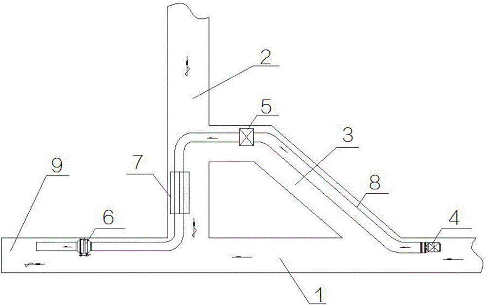
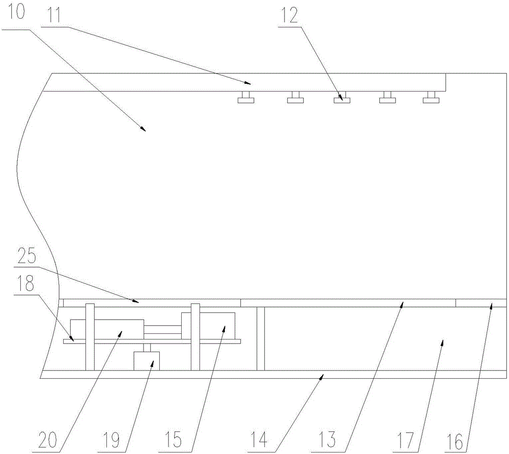
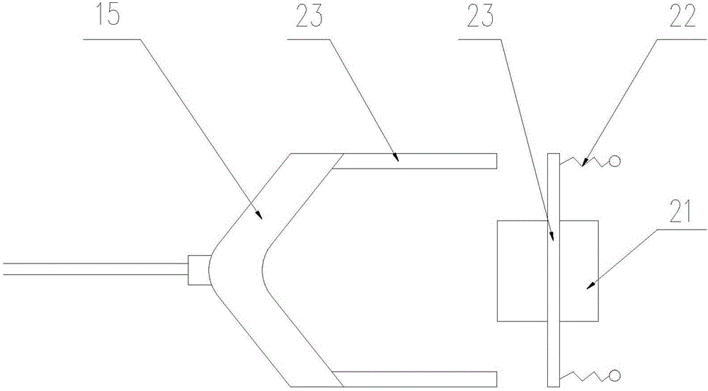
[0027] see Figure 1 to Figure 3 , is a preferred embodiment of the dust removal system based on the mine cooling system, including the tunneling tunnel 1 of the mine, the return tunnel 2 and the dehumidifier chamber 3, and one end of the tunneling tunnel 1 is the air inlet of the tunneling tunnel 1 The other end is the working site 9, the first air outlet and the second air outlet are opened on the tunneling roadway 1, the return air tunnel 2 is perpendicular to the tunneling tunnel 1, and the first air inlet is set at one end of the return air tunnel 2 , the first air inlet communicates with the first air outlet of the tunneling roadway 1, the other end of the air return roadway 2 is the air outlet end of the air return roadway 2, and a second air inlet is opened on the air return roadway 2, and the dehumidifier The air inlet end of the chamber 3 communicates with the second air outlet of the tunneling roadway 1, and the air outlet end of the dehumidifier chamber 3 communica...


PUM


Abstract

The invention aims to overcome the shortcomings of the prior art, and provides a dust removal system based on a mine cooling system, and the dust removal system is lower in investment and operating cost, and can guarantee the cooling effect and the dust removal effect at the same time. The dust removal system includes a plurality of dust removal water pipes which are arranged at an upper wall of a dust removal passage and longitudinally extend along the dust removal passage. The dust removal water pipes are respectively provided with dust removal nozzles. A dust removal steel rail is paved on the bottom wall of the dust removal passage. The dust removal steel rail comprises a walking plate and a lower base plate. A separator plate is disposed between the walking plate and the lower base plate. A dust pushing chamber and a dust collecting chamber are formed by separation of the separator plate. An installing plate is disposed in the dust pushing chamber. An elevating cylinder is disposed under the installing plate. A dust pushing oil cylinder and a V-shaped pushing head are disposed on the installing plate. The walking plate is provided with a dust leaking port. A depressed part of the pushing head is opposite to the dust leaking port and used for pushing dust on the walking plate into the dust leaking port. The walking plate is provided with an opening door corresponding to the installing plate for allowing the installing plate and the dust pushing oil cylinder and the pushing head on the installing plate to rise over the walking plate.

Description

technical field [0001] The present invention relates to the technical field of mine heat damage prevention and dust removal, in particular to a dust removal system based on a mine cooling system. Background technique [0002] During mine production, a large number of shafts have to be drilled in order to prepare new levels, new mining areas and extraction operation sites. When excavating the roadway, in order to enable the staff to breathe fresh air, dilute the gas and harmful gas and mine dust produced after the blasting at the working site, and create good climate conditions, the working site must be ventilated. At the same time, with the continuous deepening of mine mining depth, the emergence of high-temperature heat damage in mines has followed, which seriously threatens the safe production of mines, affects the physical and mental health of workers, reduces the labor productivity of workers and restricts mine production. Improvement of economic benefits. Article 102 ...

Claims


Application Information

Patent Timeline
IPC IPC(8): E21F3/00E21F5/04
CPCE21F3/00E21F5/04
Inventor 刘延宏
Owner CHONGQING HEQU JIUFENG COAL CO LTD
Why Eureka
Try Eureka