A skid-mounted quantitative loading control station
A control station and skid-mounted technology, which is applied in packaging, distribution devices, transportation and packaging, etc., can solve the problems of incomplete exhaust of degassing filter, inaccurate quantitative loading and measurement, and achieve compact structure and small footprint Less, easy to move effect
- Summary
- Abstract
- Description
- Claims
- Application Information
AI Technical Summary
Problems solved by technology
Method used
Image
Examples
Embodiment 1
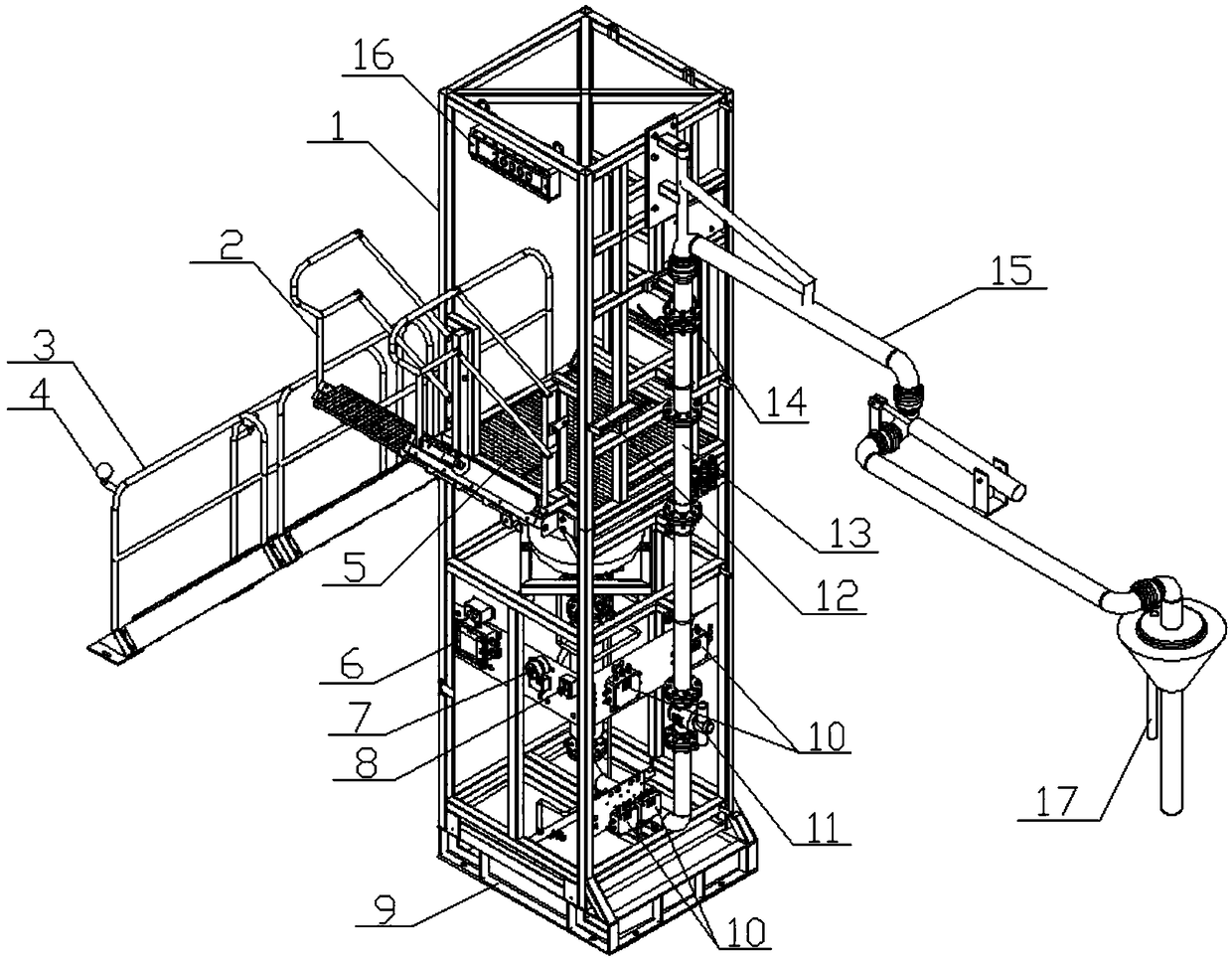
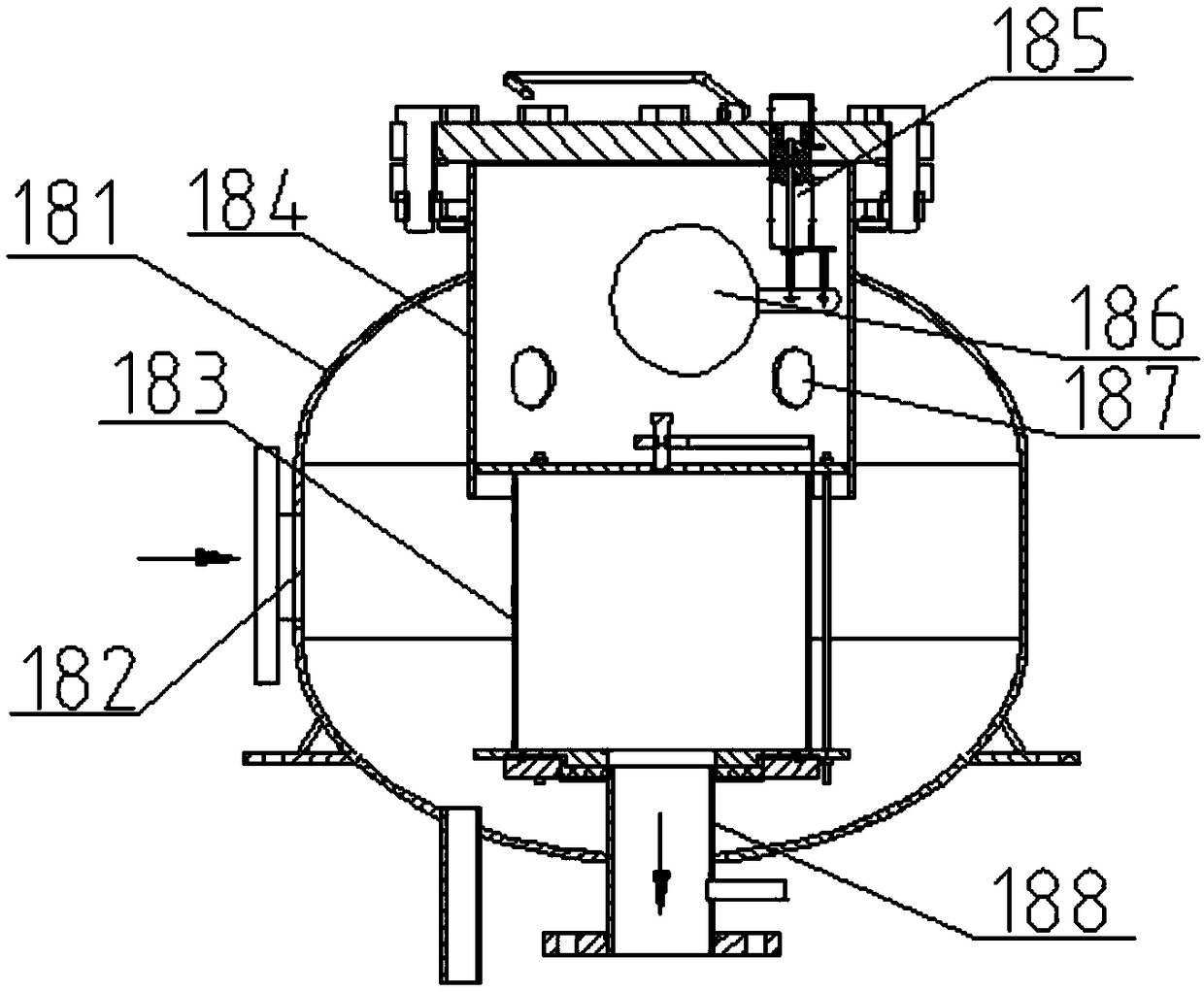
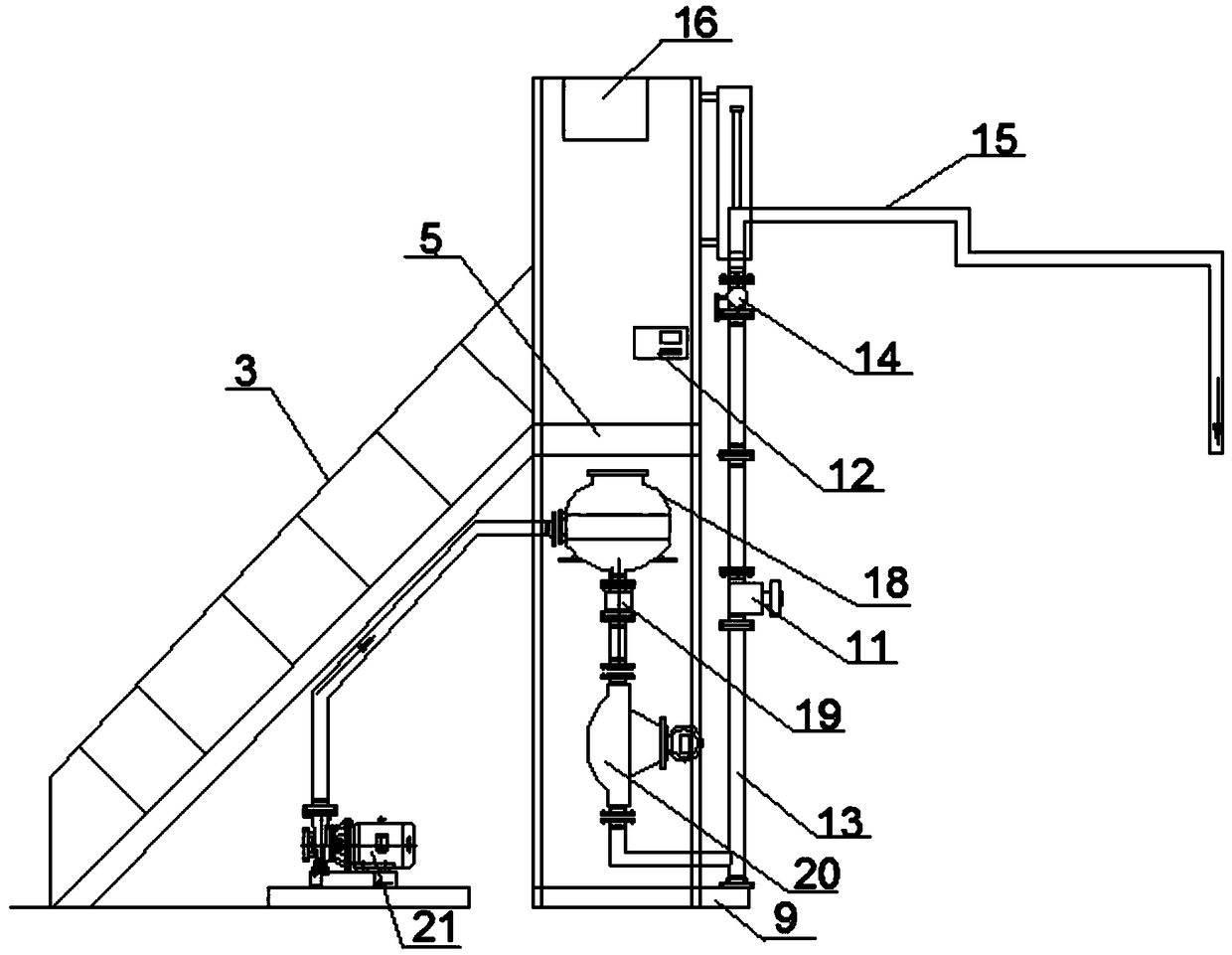
[0030] A skid-mounted quantitative loading control station, comprising a base frame 9 and a support frame 1 fixed on the base frame 9, a quantitative loading system is installed on the support frame 1, and the quantitative loading system includes a The oil inlet end connected to the supply oil tank and the crane pipe 15 used to connect with the oil tanker, the liquid phase delivery pipe 13 is arranged between the oil inlet end and the crane pipe 15, and the liquid phase delivery pipe 13 is connected from the oil inlet end to the crane pipe In the 15 direction, an oil delivery pump 21, an air elimination filter 18, a check valve 19, a flow meter 20, an electro-hydraulic valve 11 and a ball valve 14 are sequentially arranged; the air elimination filter 18 includes a cylinder 181 and a Inlet 182, the inside of the cylinder 181 is provided with a filter cartridge 183, the top of the filter cartridge 183 is fixedly connected to the exhaust device and communicated with the exhaust de...
Embodiment 2
[0033] Based on Embodiment 1, the support frame 1 is provided with a platform 5, and one side of the support frame is provided with an escalator 3, and the top of the escalator 3 is connected with the platform 5; the degassing filter 18, check valve 19 and flowmeter 20 They are all located below the platform 5, the oil delivery pump 21 is located below the escalator 3, and the liquid phase delivery pipe 13 connected to the outlet of the flowmeter 20 extends from the inside of the support frame to the outside of the support frame and is bent upward and fixed on the opposite side of the support frame to the escalator 3 , the column of the crane tube 15 is fixed on the upper end of the support frame and connected with the end of the liquid phase delivery pipe 13 . The control station assembles valves, oil pump 21, air filter 18, flow meter 20, and control system together with the support frame 1. It has a compact structure and a small footprint. Yes, it is easy to operate and eas...
Embodiment 3
[0035] Based on Embodiment 1, the quantitative loading system further includes a batch controller 12 , and the oil delivery pump 21 , flow meter 20 , electro-hydraulic valve 11 and ball valve 14 are all connected to the batch controller 12 . To start the quantitative loading system, the operator pulls the crane tube 15 and slowly puts the crane tube 15 into the tank truck, and then starts the batch controller 12. The batch controller 12 controls the opening of the electro-hydraulic valve 11 and the ball valve 14, and transmits the signal to Oil delivery pump 21, the oil delivery pump 21 starts to work after receiving the signal, and transports the oil in the oil supply tank to the degassing filter 18. After the oil passes through the degassing filter 18, the solid impurities and gases contained in it are discharged, and then enter the flow A meter 20, the flow meter 20 measures the flow of oil and feeds the flow signal back to the batch controller 12. The batch controller 12 c...
PUM
 Abstract
Description
Claims
Application Information
 - R&D
- Intellectual Property
- Life Sciences
- Materials
- Tech Scout
- Unparalleled Data Quality
- Higher Quality Content
- 60% Fewer Hallucinations
Browse by: Latest US Patents, China's latest patents, Technical Efficacy Thesaurus, Application Domain, Technology Topic, Popular Technical Reports.
© 2025 PatSnap. All rights reserved.Legal|Privacy policy|Modern Slavery Act Transparency Statement|Sitemap|About US| Contact US: help@patsnap.com


