Adjusting device for powder transportation

A technology of adjusting device and material conveying, which is applied in the directions of transportation and packaging, conveying bulk materials, conveyors, etc., can solve the problem of inability to adjust the material speed, and achieve the effect of improving efficiency, simple device structure, and automatically adjusting the cutting speed.

Inactive Publication Date: 2017-05-31
安徽金鼎新材料有限公司
View PDF0 Cites 2 Cited by
  • Summary
  • Abstract
  • Description
  • Claims
  • Application Information

AI Technical Summary

Problems solved by technology

[0003] The technical problem to be solved by the present invention is to provide a powder conveying adjustment device to solve the problem that the existing electric butterfly valve for powder conveying can only be controlled by switches but cannot adjust the material speed

Method used


Image

  • Adjusting device for powder transportation
  • Adjusting device for powder transportation

Examples


Embodiment Construction

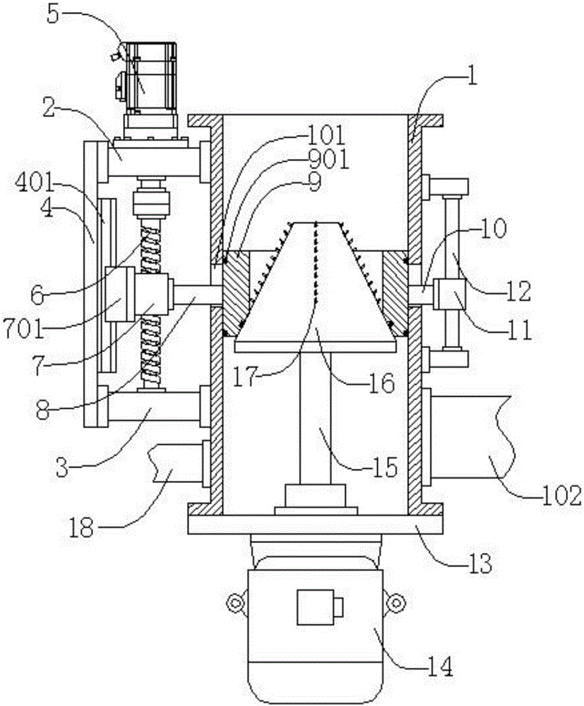
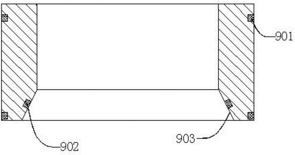
[0030] Such as figure 1 , figure 2As shown, a powder feeding adjustment device includes a pipe body 1, an upper support seat 2, a lower support seat 3, a support plate 4, a servo motor 5, a lead screw 6, a feed nut 7, a left connecting rod 8, a slide Cover 9, right connecting rod 10, guide block 11, guide rod 12, blocking plate 13, motor 14, rotating shaft 15, conical blanking head 16, several rake nails 17, air duct 18, the upper support seat 2 Located at the upper left side of the pipe body 1, the upper support seat 2 is threadedly connected with the pipe body 1, and the lower support seat 3 is located at the left lower end of the pipe body 1, and the lower support seat 3 is threadedly connected with the pipe body 1 , the support plate 4 is located on the left side of the upper support base 2 and on the left side of the lower support base 3, the support plate 4 is threaded with the upper support base 2 and connected with the lower support base 3, and the servo motor 5 is ...


PUM


Abstract

The invention discloses an adjusting device for powder transportation. The adjusting device comprises a pipe body, an upper supporting seat, a lower supporting seat, a supporting plate, a servo motor, a screw rod, a feed nut, a left connecting rod, a sliding sleeve, a right connecting rod, a guide block, a guide rod, a plug plate, a motor, a rotating shaft, a tapered discharge head, a plurality of harrow pins and an air pipe, wherein the servo motor drives the feed nut to move upwards through the screw rod, the sliding sleeve is driven to move upwards along the guide rod, and a tapered transition surface arranged on the sliding sleeve and the tapered discharge head are separated; the angle of the servo motor is arranged, so that the distance between the tapered transition surface and the tapered discharge head can be adjusted, and the discharge speed is adjusted; the motor drives the tapered discharge head to rotate through the rotating shaft; the harrow pins arranged on the tapered discharge head scatter powder falling from the sliding sleeve; compressed air is input into the pipe body through the air pipe; and compressed air discharges powder from a conveying pipe. According to the adjusting device, the structure is simple, the discharge speed can be automatically adjusted, caked powder can be scattered, and the powder modification efficiency is improved.

Description

technical field [0001] The invention relates to a powder auxiliary production device, in particular to a powder feeding regulating device. Background technique [0002] The powder surface is treated by physical or chemical methods, and the physical and chemical properties of the surface are purposely changed to meet the specific requirements of use. The surface modification of the powder is widely used in papermaking, Modified calcium carbonate in plastics, plastic films, chemical fibers, rubber, adhesives, sealants, daily chemicals, cosmetics, building materials, coatings, paints, inks, putty, sealing wax, medicine, food (such as chewing gum, chocolate), feed General production process: cleaning, drying, crushing, stockpiling, grinding, grading, modification, packaging. During the production of modified calcium carbonate, the raw materials are generally stored in the silo. The existing method uses Roots blower to extract the silo. The raw materials are transported to the m...

Claims


Application Information

Patent Timeline
Patent Type & Authority Applications(China)
IPC IPC(8): B65G53/40
CPCB65G53/40
Inventor 常珍国
Owner 安徽金鼎新材料有限公司
Why Eureka
Try Eureka