Spherical material supplying mechanism

A feeding mechanism and material technology, which is applied to conveyors, conveyor objects, transportation and packaging, etc., can solve the problems of difficult operation, difficulty, easy generation of powder particles, etc., and achieve stable operation performance and save the number of operators. Effect

Active Publication Date: 2017-05-31
DALIAN YUN MING AUTOMATION TECH
View PDF4 Cites 2 Cited by
  • Summary
  • Abstract
  • Description
  • Claims
  • Application Information

AI Technical Summary

Problems solved by technology

However, the existing way of disc vibrating plate vibration cannot provide spherical materials of various sizes and materials at the same time
In addition, in the process of feeding with disc vibrating disc, spherical materials collide and rub against each other in the vibrating disc for a long time, which is easy to produce powder particles, which affects the stability of other production processes
[0003] In addition, in the past, some spherical material feeding mechanisms used manual operations, manual operations, difficult operations, manual operations that are prone to visual fatigue, and easy misoperations and other conditions and difficulties.

Method used


Image

  • Spherical material supplying mechanism
  • Spherical material supplying mechanism
  • Spherical material supplying mechanism

Examples


Embodiment 1

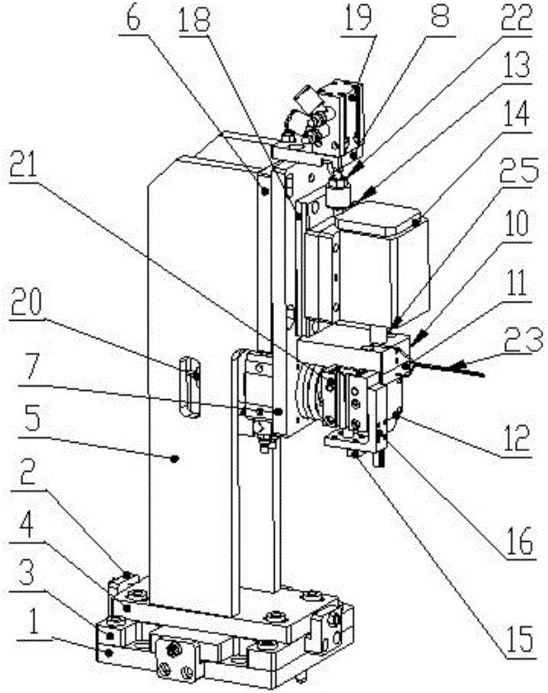
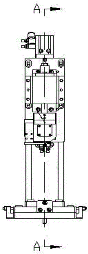
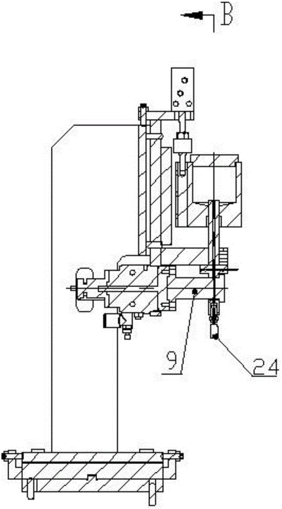
[0020] A spherical material feeding mechanism, comprising: mounting vertical plate 5, height adjustment plate 6, rotary cylinder mounting plate 7, cylinder mounting plate 8, material distribution shaft 9, guide shaft fixing plate 10, ball guide block 11, ball stopper Plate 12, slider mounting plate 13, ball bin 14, cylinder driving plate 15, blanking rod 16, cylinder Ⅰ19, swing table 20, cylinder Ⅱ21, floating joint 22, guide column additional processing inclined surface 25, linear guide rail 18; height The adjustment plate 6 is fixed on the side of the installation vertical plate 5, the rotary cylinder mounting plate 7 is located on the height adjustment plate 6, and there is an adjustment in the Z-axis direction, the cylinder mounting plate 8 is fixed on the rotary cylinder mounting plate 7, and the cylinder I19 is set on the cylinder On the mounting plate 8; the linear guide rail 18 is located on the rotary cylinder mounting plate 7, the slider mounting plate 13 is set on th...


PUM


Abstract

A spherical material supplying mechanism comprises installation stand plates, a height adjusting plate, a rotation air cylinder installation plate, an air cylinder installation plate, a material distributing shaft, a guide shaft fixing plate, a sphere guiding block, a sphere baffle, a sliding block installation plate, a spherical material bin, an air cylinder driving plate, a material falling rod, an air cylinder I, a swing platform, an air cylinder II, a floating connector, a guide column additionally-machined inclined face and a linear guide rail. The height adjusting plate is fixed to the side faces of the installation stand plates. The rotation air cylinder installation plate is located on the height adjusting plate, and the adjustment allowance exists in the Z-axis direction. After a certain number of workpiece spheres are manually fed into the spherical material supplying mechanism, the spherical material supplying mechanism can automatically supply the materials, distribute the materials and feed the materials and is stable in operation performance and high in efficiency.

Description

technical field [0001] The invention relates to the technical field of manufacturing a spherical material feeding mechanism, in particular to a spherical material feeding mechanism. Background technique [0002] The traditional spherical material feeding mechanism usually uses a disc vibrating vibrator to vibrate and feed. However, the existing disc vibrating disc vibration method cannot provide spherical materials of various sizes and materials at the same time. In addition, in the process of feeding with disc vibrating disc, spherical materials collide and rub against each other in the vibrating disc for a long time, which easily produces powder particles and affects the stability of other production processes. [0003] In addition, in the past, some spherical material feeding mechanisms used manual operations, manual operations, difficult operations, manual operations that were prone to visual fatigue, and easy misoperations. Contents of the invention [0004] Aiming ...

Claims


Application Information

Patent Timeline
Patent Type & Authority Applications(China)
IPC IPC(8): B65G47/14
CPCB65G47/1407B65G2201/02
Inventor 王承刚田志涛逄锦丽
Owner DALIAN YUN MING AUTOMATION TECH
Why Eureka
Try Eureka